1KD-FTV ENGINE MECHANICAL ENGINE UNIT REMOVAL
PROCEDURE

 27020
1.REMOVE GENERATOR ASSEMBLY
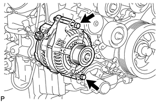
Remove the 2 bolts and generator.
12511C
2.REMOVE GENERATOR BRACKET
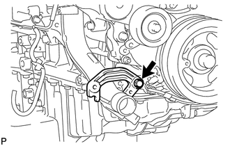
Remove the bolt and generator bracket.
88431
3.REMOVE NO. 1 COMPRESSOR MOUNTING BRACKET
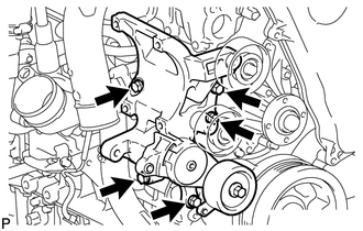
Remove the 5 bolts and No. 1 compressor mounting bracket.
12229
4.REMOVE VENTILATION PIPE
15301
5.REMOVE ENGINE OIL LEVEL DIPSTICK GUIDE
17274
6.REMOVE COMPRESSOR INLET ELBOW
17271
7.REMOVE NO. 1 TURBO INSULATOR
17167
8.REMOVE NO. 1 EXHAUST MANIFOLD HEATINSULATOR
16284
9.DISCONNECT NO. 1 TURBO WATER HOSE
17291
10.REMOVE TURBINE OUTLET ELBOW
17293
11.REMOVE TURBOCHARGER STAY
15407
12.REMOVE TURBO OIL INLET PIPE SUB-ASSEMBLY
17141
13.REMOVE EXHAUST MANIFOLD WITH TURBOCHARGER
11202D
14.REMOVE NO. 2 CYLINDER HEAD COVER SUB-ASSEMBLY
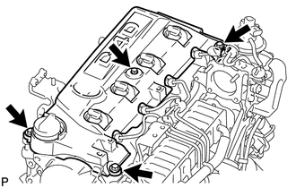
Remove the 4 bolts and No. 2 cylinder head cover.
17298
15.REMOVE COMPRESSOR ELBOW STAY
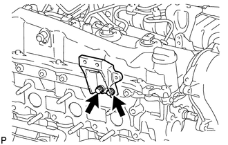
Remove the 2 bolts and compressor elbow stay.
16321
16.REMOVE WATER INLET
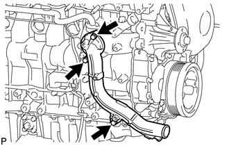
Remove the 3 bolts and water inlet.
16331A
17.REMOVE THERMOSTAT
Remove the thermostat.
Remove the gasket from the thermostat.
16207
18.REMOVE NO. 2 WATER BY-PASS PIPE SUB-ASSEMBLY
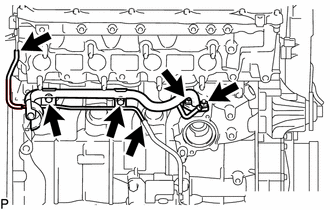
Disconnect the 2 hoses.
Remove the 2 bolts, 2 nuts and No. 2 water by-pass pipe.
89491
19.REMOVE ENGINE OIL LEVEL SENSOR
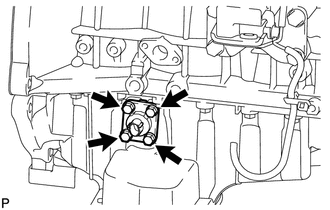
Remove the 4 bolts and engine oil level sensor.
Cut away part of the gasket and remove the gasket from the engine oil level sensor.
- HINT:
-
Remove only the outer part of the gasket.
11336A
20.REMOVE TIMING GEAR COVER INSULATOR
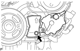
Remove the bolt and gear cover insulator.
29300
21.REMOVE VACUUM PUMP ASSEMBLY
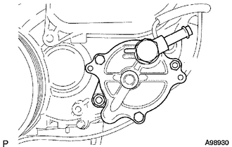
Remove the 2 nuts, vacuum pump and 2 O-rings.
44310
22.REMOVE VANE PUMP ASSEMBLY
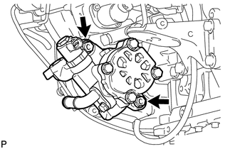
Remove the 2 nuts, vane pump and O-ring.
89422C
23.REMOVE ENGINE COOLANT TEMPERATURE SENSOR
11301L
24.REMOVE CAMSHAFT POSITION SENSOR
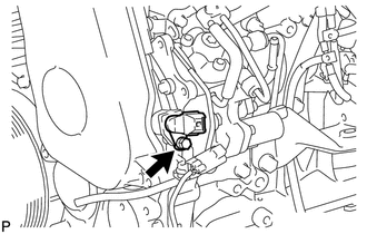
Remove the bolt and camshaft position sensor.
11301K
25.REMOVE CRANKSHAFT POSITION SENSOR
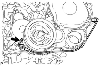
Detach the clamp and remove the bolt and crankshaft position sensor.
11322A
26.REMOVE NO. 1 TIMING BELT COVER
13568
27.REMOVE TIMING BELT
13505
28.REMOVE NO. 1 TIMING BELT IDLER SUB-ASSEMBLY
13471
29.REMOVE CRANKSHAFT PULLEY
16267
30.DISCONNECT NO. 3 WATER BY-PASS HOSE (w/ EGR System with EGR Cooler)
16281
31.DISCONNECT NO. 4 WATER BY-PASS HOSE (w/ EGR System with EGR Cooler)
32.REMOVE INJECTION PIPE (w/ EGR System)
17871A
33.REMOVE AIR CONNECTOR STAY (w/ EGR System)
25625
34.REMOVE EGR VALVE BRACKET (w/ EGR System)
35.REMOVE ELECTRIC VACUUM REGULATING VALVE ASSEMBLY (w/ EGR System)
17862A
36.REMOVE NO. 2 INTAKE AIR CONNECTOR (w/ EGR System)
17861F
37.REMOVE INTAKE AIR CONNECTOR (w/ EGR System)
25800
38.REMOVE ELECTRIC EGR CONTROL VALVE ASSEMBLY WITHNO. 2 EGR VALVE AND EGR COOLER (w/ EGR System with EGR Cooler)
25800
39.REMOVE ELECTRIC EGR CONTROL VALVEASSEMBLY WITH NO. 1 EGR PIPE SUB-ASSEMBLY (w/ EGR System without EGR Cooler)
25800
40.REMOVE ELECTRIC EGR CONTROL VALVE ASSEMBLY (w/ EGR System)
25624
41.REMOVE EGR VALVE ADAPTER (w/ EGR System with EGR Cooler)
25630
42.REMOVE NO. 2 EGR VALVE ASSEMBLY (w/ EGR System with EGR Cooler)
22267A
43.REMOVE THROTTLE BODY BRACKET (w/o EGR System)
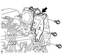
Disconnect the vacuum hose.
Remove the bolt and gas filter with gas filter bracket.
Remove the 2 bolts and throttle body bracket.
44.REMOVE INJECTION PIPE (w/o EGR System)
17871A
45.REMOVE AIR CONNECTOR STAY (w/o EGR System)
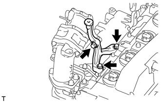
Remove the 3 bolts and air connector stay.
17862A
46.REMOVE NO. 2 INTAKE AIR CONNECTOR (w/o EGR System)
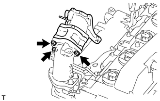
Remove the 3 nuts.
Remove the No. 2 intake air connector, No. 1 intake air connector and 2 gaskets.
17861F
47.REMOVE INTAKE AIR CONNECTOR (w/o EGR System)
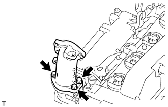
Remove the 3 bolts, intake air connector and gasket.
25617A
48.REMOVE NO. 2 EGR HOLE COVER PLATE (w/o EGR System)
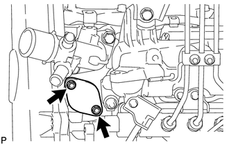
Remove the 2 nut, gasket and No. 2 EGR hole cover plate.
16331
49.REMOVE WATER OUTLET
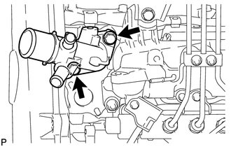
Remove the 2 bolts, gasket and water outlet.
19871
50.REMOVE NO. 1 GLOW PLUG CONNECTOR
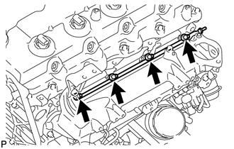
Remove the 4 screw grommets, 4 nuts and No. 1 glow plug connector.
17135A
51.REMOVE NO. 1 INTAKE MANIFOLD INSULATOR
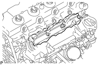
Remove the No. 1 intake manifold insulator.
19850
52.REMOVE GLOW PLUG ASSEMBLY
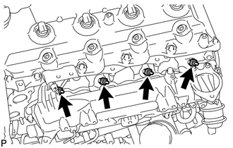
Using a 12 mm deep socket wrench, remove the 4 glow plugs.
17118
53.REMOVE MANIFOLD STAY WITH VACUUMSWITCHING VALVE
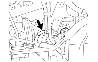
Disconnect the No. 1 vacuum transmitting hose.
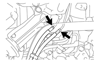
w/ EGR System:
Disconnect the No. 2 vacuum transmitting hose and No. 3 vacuum transmitting hose assembly.
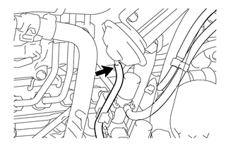
w/ EGR Cooler:
Disconnect the No. 3 vacuum transmitting hose.
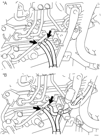
Disconnect the No. 3 vacuum transmitting hose assembly and No. 4 vacuum transmitting hose assembly.
| *A | w/o EGR System |
| *B | w/ EGR System |
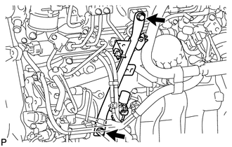
Remove the 2 bolts and manifold stay with vacuum switching valve.
17138A
54.REMOVE INTAKE PIPE STAY
25804
55.REMOVE VACUUM CONTROL VALVE SET
23704
56.REMOVE NO. 4 INJECTION PIPE SUB-ASSEMBLY
23770
57.REMOVE NO. 2 NOZZLE LEAKAGE PIPE ASSEMBLY
17118B
58.REMOVE INTAKE MANIFOLD INSULATOR
17111
59.REMOVE INTAKE MANIFOLD
17136
60.REMOVE NO. 2 INTAKE MANIFOLD INSULATOR
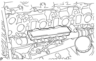
Remove the No. 2 intake manifold insulator.
23804C
61.REMOVE FUEL INLET PIPE SUB-ASSEMBLY
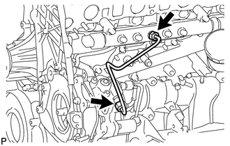
Loosen the union nuts and remove the fuel inlet pipe.
23810A
62.REMOVE COMMON RAIL ASSEMBLY
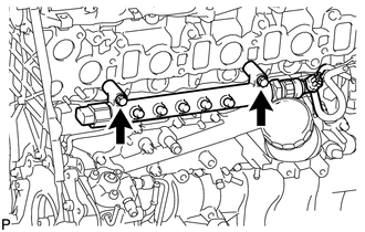
Remove the 2 bolts and common rail.
- NOTICE:
-
Do not remove the pressure discharge valve or fuel pressure sensor.
22100
63.REMOVE SUPPLY PUMP ASSEMBLY
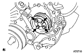
Remove the 4 bolts indicated by the arrows in the illustration.
Remove the No. 2 camshaft timing pulley flange and pump drive shaft pulley.
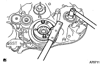
Remove the set nut and O-ring while holding the crankshaft pulley using SST.
- SST
- 09213-58014
09330-00021
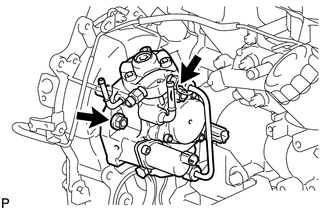
Loosen the 2 nuts.
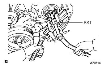
Using SST, disconnect the supply pump from the injection gear.
- SST
- 09950-50013 (09951-05010, 09952-05010, 09953-05020, 09954-05021)
- NOTICE:
-
Apply lubricant to the threads and tip of SST (center bolt) before using it.
Remove the 2 nuts and supply pump.
- NOTICE:
- ·
Do not hold or carry the fuel supply pump by holding the pipe.
·The fuel supply pump must be kept horizontal.
Remove the O-ring.
22813
64.REMOVE NO. 1 INJECTION PUMP PROTECTOR
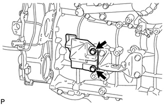
Remove the 2 bolts and No. 1 injection pump protector.
15601
65.REMOVE OIL FILTER SUB-ASSEMBLY
25708
66.REMOVE NO. 3 VACUUM TRANSMITTING PIPE SUB-ASSEMBLY
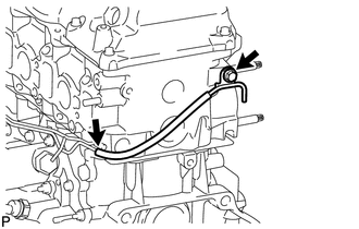
Disconnect the vacuum hose.
Remove the bolt and No. 3 vacuum transmitting pipe.
25707
67.REMOVE NO. 2 VACUUM TRANSMITTING PIPE SUB-ASSEMBLY
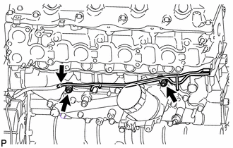
Disconnect the vacuum hose.
Remove the 2 nuts and No. 2 vacuum transmitting pipe.
15701C
68.REMOVE OIL COOLER COVER SUB-ASSEMBLY
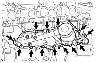
Remove the 13 bolts and oil cooler cover.
25706
69.REMOVE NO. 1 VACUUM TRANSMITTING PIPE SUB-ASSEMBLY
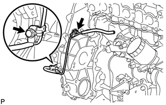
Remove the bolt, nut and No. 1 vacuum transmitting pipe.
12104
70.REMOVE NO. 1 OIL PAN COVER SUB-ASSEMBLY
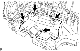
Remove the 4 bolts and No. 1 oil pan cover.
25733A
71.REMOVE NO. 1 VACUUM PIPE
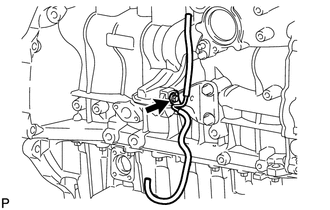
Remove the bolt and No. 1 vacuum pipe.
12582
72.REMOVE NO. 2 CYLINDER BLOCK INSULATOR
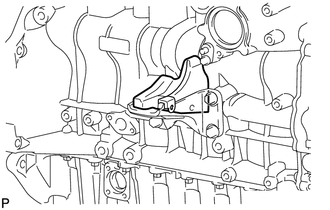
Remove the No. 2 cylinder block insulator.
12311
73.REMOVE FRONT NO. 1 ENGINE MOUNTING BRACKET RH
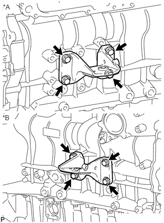
Remove the 8 bolts and 2 engine mounting brackets.
| *A | for LH Side |
| *B | for RH Side |