SUSPENSION CONTROL AIR SUSPENSION SYSTEM C1715/15 Front Acceleration Sensor RH Malfunction C1716/16 Front Acceleration Sensor LH Malfunction C1717/17 Rear Acceleration Sensor Malfunction C1796/96 (Up & Down) G Sensor FR C1797/97 (Up & Down) G Sensor FL C1798/98 (Up & Down) G Sensor Rear
DESCRIPTION
The acceleration sensor (up and down G sensor) detects the upward and downward acceleration of the vehicle, and outputs it as a voltage to the suspension control ECU. Up and down G sensors are installed in 3 locations: 1) the suspension control ECU, 2) the RH side instrument panel, and 3) behind the deck trim side panel assembly LH. Each up and down G sensor independently detects the upward and downward acceleration. During a test mode inspection, the suspension control ECU reads the fluctuations in each sensor signal. If a sensor signal does not fluctuate, test mode DTCs C1796/96, C1797/97 and C1798/98 are stored.
| DTC Code | DTC Detection Condition | Trouble Area |
|---|---|---|
| C1715/15 | Either condition is met:
·
With the ignition switch ON, a voltage of 5.5 V or higher or 4.3 V or less at the power source of the front acceleration sensor RH is detected for 0.5 seconds. ·
With the ignition switch ON, a voltage of 4.7 V or higher or 0.3 V or less at the front acceleration sensor RH is detected for 1 second. |
·
Harness or connector ·
Front acceleration sensor RH ·
Suspension control ECU |
| C1716/16 | Either condition is met:
·
With the ignition switch ON, a voltage of 5.5 V or higher or 4.3 V or less at the power source of the front acceleration sensor LH is detected for 0.5 seconds. ·
With the ignition switch ON, a voltage of 4.7 V or higher or 0.3 V or less at the front acceleration sensor LH is detected for 1 second. |
Suspension control ECU (Front acceleration sensor LH) |
| C1717/17 | Either condition is met:
·
With the ignition switch ON, a voltage of 5.5 V or higher or 4.3 V or less at the power source of the rear acceleration sensor is detected for 0.5 seconds. ·
With the ignition switch ON, a voltage of 4.7 V or higher or 0.3 V or less at the rear acceleration sensor is detected for 1 second. |
·
Harness or connector ·
Rear acceleration sensor ·
Suspension control ECU |
| C1796/96 | On a level surface, the G sensor input is +/- 1.96 m/s2 or more for 1 second or more. | ·
Harness or connector ·
Front acceleration sensor RH ·
Suspension control ECU |
| C1797/97 | On a level surface, the G sensor input is +/- 1.96 m/s2 or more for 1 second or more. | Suspension control ECU (Front acceleration sensor LH) |
| C1798/98 | On a level surface, the G sensor input is +/- 1.96 m/s2 or more for 1 second or more. | ·
Harness or connector ·
Rear acceleration sensor ·
Suspension control ECU |
- HINT:
-
If DTCs C1716/16 and C1797/97 are output, replace the suspension control ECU (houses the front acceleration sensor LH).
WIRING DIAGRAM
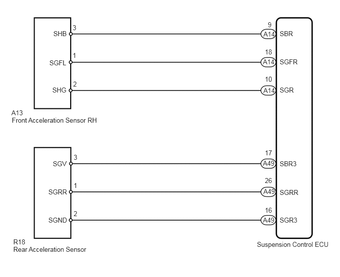
CAUTION / NOTICE / HINT
- NOTICE:
-
When replacing the suspension control ECU, perform registration (See page Suspension>SUSPENSION CONTROL>AIR SUSPENSION SYSTEM>REGISTRATION).
PROCEDURE
Turn the ignition switch off.
Connect the intelligent tester to the DLC3.
Turn the ignition switch to ON.
Turn the intelligent tester on.
Enter the following menus: Chassis / Air suspension / Data List.
| Tester Display | Measurement Item/Range | Normal Condition | Diagnostic Note |
|---|---|---|---|
| (Up & Down) G Sensor FR | (Up & Down) G sensor (Front RH)/
Min.: -1045.29 m/s2 Max.: 1045.26 m/s2 |
0 +/- 0.98 m/s2 when stationary | The value changes when the vehicle (Front RH) is bounced. |
| (Up & Down) G Sensor FL | (Up & Down) G sensor (Front LH)/
Min.: -1045.29 m/s2 Max.: 1045.26 m/s2 |
0 +/- 0.98 m/s2 when stationary | The value changes when the vehicle (Front LH) is bounced. |
| (Up & Down) G Sensor Rear | (Up & Down) G sensor (Rear)/
Min.: -1045.29 m/s2 Max.: 1045.26 m/s2 |
0 +/- 0.98 m/s2 when stationary | The value changes when the vehicle (rear) is bounced. |
- OK:
Acceleration value changes.
OK
(See pageGeneral>INTRODUCTION>HOW TO TROUBLESHOOT ECU CONTROLLED SYSTEMS>HOW TO PROCEED WITH TROUBLESHOOTING)
NG
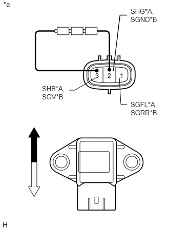
| *A | for Front RH |
| *B | for Rear |
| *a | Component without harness connected
(Acceleration Sensor) |

|
Upside |

|
Downside |
Check the front acceleration sensor RH (when DTC C1715/15 or C1796/96 is output).
Remove the front acceleration sensor RH (See page Suspension>SUSPENSION CONTROL>FRONT ACCELERATION SENSOR>REMOVAL).
Connect 3 dry cell batteries of 1.5 V in series.
Connect the positive (+) end of the batteries to terminal 3 (SHB) of the acceleration sensor and the negative (-) end of the batteries to terminal 2 (SHG). Then measure the voltage between terminal 1 (SGFL) and terminal 2 (SHG).
Measure the voltage according to the value(s) in the table below.
- Standard Voltage:
Tester Connection Condition Specified Condition 1 (SGFL) - 2 (SHG) Sensor in vertical position Approx. 2.0 to 2.5 V Sensor tilted left or right from vertical position Changes between approx. 0.9 and 2.3 V
Check the rear acceleration sensor: (when DTC C1717/17 or C1798/98 is output).
Remove the rear acceleration sensor (See page Suspension>SUSPENSION CONTROL>REAR ACCELERATION SENSOR>REMOVAL).
Connect 3 dry cell batteries of 1.5 V in series.
Connect the positive (+) end of the batteries to terminal 3 (SGV) of the acceleration sensor and the negative (-) end of the batteries to terminal 2 (SGND). Then measure the voltage between terminal 1 (SGRR) and terminal 2 (SGND).
Measure the voltage according to the value(s) in the table below.
- Standard Voltage:
Tester Connection Condition Specified Condition 1 (SGRR) - 2 (SGND) Sensor in vertical position Approx. 2.0 to 2.5 V Sensor tilted left or right from vertical position Changes between approx. 0.9 and 2.3 V
- NOTICE:
-
Do not apply a voltage of higher than 6 V.
- HINT:
-
When the acceleration sensor is tilted, it may output a different value.
| Result | Proceed to |
|---|---|
| OK | A |
| NG (Front acceleration sensor RH) | B |
| NG (Rear acceleration sensor) | C |
A
B
C
Check the front acceleration sensor RH (when DTC C1715/15 or C1796/96 is output).
Disconnect the A13 front acceleration sensor RH connector.
Disconnect the A14 suspension control ECU connector.
Measure the resistance according to the value(s) in the table below.
- Standard Resistance:
Tester Connection Condition Specified Condition A13-1 (SGFL) - A14-18 (SGFR) Always Below 1 Ω A13-2 (SHG) - A14-10 (SGR) Always Below 1 Ω A13-3 (SHB) - A14-9 (SBR) Always Below 1 Ω A13-1 (SGFL) - Body ground Always 10 kΩ or higher A13-2 (SHG) - Body ground Always 10 kΩ or higher A13-3 (SHB) - Body ground Always 10 kΩ or higher
Check the rear acceleration sensor: (when DTC C1717/17 or C1798/98 is output).
Disconnect the R18 rear acceleration sensor connector.
Disconnect the A49 suspension control ECU connector.
Measure the resistance according to the value(s) in the table below.
- Standard Resistance:
Tester Connection Condition Specified Condition R18-1 (SGRR) - A49-26 (SGRR) Always Below 1 Ω R18-2 (SGND) - A49-16 (SGR3) Always Below 1 Ω R18-3 (SGV) - A49-17 (SBR3) Always Below 1 Ω R18-1 (SGRR) - Body ground Always 10 kΩ or higher R18-2 (SGND) - Body ground Always 10 kΩ or higher R18-3 (SGV) - Body ground Always 10 kΩ or higher
OK
NG