Home › Engine / Hybrid System › 1KD-FTV (ENGINE CONTROL) › ECD SYSTEM › 2017.08–2020.08
RM27T0E _51 Engine / Hybrid System _053659 1KD-FTV ENGINE CONTROL _0260458 ECD SYSTEM J

1KD-FTV ENGINE CONTROL  ECD SYSTEM  VC Output Circuit  


DESCRIPTION

The ECM constantly generates 5 V of power from the battery voltage supplied to the +B (BATT) terminal to operate the microprocessor. The ECM also provides this power to the sensors through the VC output circuit.
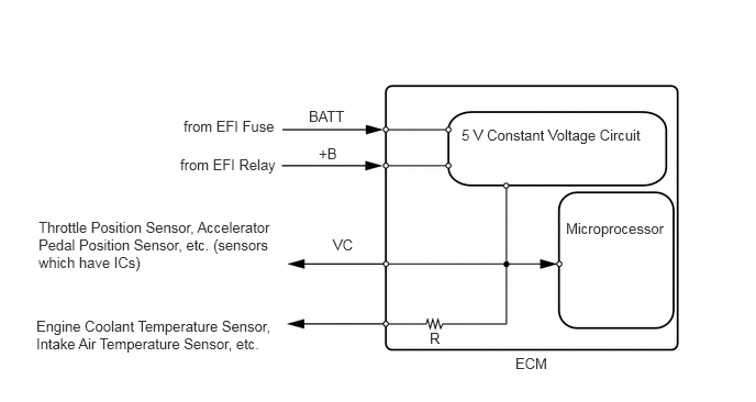
A206916E71
4.375,1.198 6.198,1.375 1.823,0.177 10 false 5 V Constant Voltage Circuit 5.365,2.083 6.417,2.323 1.052,0.24 10 false Microprocessor 1.74,1.115 2.844,1.292 1.104,0.177 10 false from EFI Fuse 1.708,1.479 2.844,1.698 1.135,0.219 10 false from EFI Relay 2.927,1.021 3.448,1.24 0.521,0.219 10 false BATT 0.365,2.073 2.688,2.615 2.323,0.542 10 false Throttle Position Sensor, Accelerator Pedal Position Sensor, etc. (sensors which have ICs) 0.344,3.01 2.708,3.438 2.365,0.427 10 false Engine Coolant Temperature Sensor, Intake Air Temperature Sensor, etc. 4.073,3.125 4.333,3.333 0.26,0.208 10 false R 3.021,1.375 3.302,1.573 0.281,0.198 10 false +B 3.156,2.24 3.427,2.438 0.271,0.198 10 false VC 4.885,3.365 5.333,3.594 0.448,0.229 10 false ECM

When the VC circuit is short-circuited, the microprocessor in the ECM and sensors that are supplied with power through the VC circuit are inactivated because the power is not supplied from the VC circuit. Under this condition, the system does not start up and the MIL does not illuminate even if the system malfunctions.

HINT:

Under normal conditions, the MIL is illuminated for several seconds when the ignition switch is first turned to ON. The MIL goes off when the engine is started.


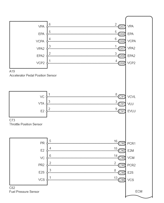
WIRING DIAGRAM

·

VC Output Circuit


A227787E04
0.406,8.125 0.719,8.333 0.313,0.208 10 false C82 0.406,8.292 1.844,8.479 1.438,0.188 10 false Fuel Pressure Sensor 0.406,3.031 0.698,3.188 0.292,0.156 10 false A19 0.417,3.208 2.667,3.438 2.25,0.229 10 false Accelerator Pedal Position Sensor 0.406,5.167 0.74,5.365 0.333,0.198 10 false C73 0.406,5.344 1.958,5.531 1.552,0.188 10 false Throttle Position Sensor 1.677,1.396 1.979,1.583 0.302,0.188 10 false EPA 1.604,2.354 1.979,2.542 0.375,0.188 10 false EPA2 1.604,2.042 2,2.229 0.396,0.188 10 false VPA2 1.573,1.719 2,1.906 0.427,0.188 10 false VCPA 1.677,1.073 1.979,1.26 0.302,0.188 10 false VPA 1.594,2.667 1.99,2.854 0.396,0.188 10 false VCP2 2.135,0.979 2.292,1.167 0.156,0.188 10 false 6 2.135,1.302 2.292,1.49 0.156,0.188 10 false 5 2.135,1.615 2.292,1.802 0.156,0.188 10 false 4 2.135,1.938 2.292,2.125 0.156,0.188 10 false 3 2.135,2.25 2.292,2.438 0.156,0.188 10 false 2 2.135,2.573 2.292,2.76 0.156,0.188 10 false 1 2.115,4.042 2.271,4.229 0.156,0.188 10 false 1 5.021,1.938 5.177,2.125 0.156,0.188 10 false 1 5.021,0.979 5.177,1.167 0.156,0.188 10 false 2 5.021,1.302 5.177,1.49 0.156,0.188 10 false 5 5.021,1.615 5.177,1.802 0.156,0.188 10 false 6 5.021,2.26 5.177,2.448 0.156,0.188 10 false 3 5.042,2.573 5.198,2.76 0.156,0.188 10 false 4 5.573,1.396 5.885,1.583 0.313,0.188 10 false EPA 5.573,2.354 5.99,2.542 0.417,0.188 10 false EPA2 5.573,2.021 5.969,2.208 0.396,0.188 10 false VPA2 5.573,1.708 5.99,1.896 0.417,0.188 10 false VCPA 5.573,1.063 5.885,1.25 0.313,0.188 10 false VPA 5.563,2.667 5.958,2.854 0.396,0.188 10 false VCP2 5.198,2.042 5.49,2.229 0.292,0.188 10 false G57 5.198,1.083 5.5,1.271 0.302,0.188 10 false G57 5.198,2.677 5.49,2.865 0.292,0.188 10 false G58 5.198,2.354 5.479,2.542 0.281,0.188 10 false G58 5.198,1.719 5.5,1.906 0.302,0.188 10 false G58 5.198,1.406 5.5,1.594 0.302,0.188 10 false G58 2.115,4.354 2.271,4.542 0.156,0.188 10 false 3 2.115,4.677 2.271,4.865 0.156,0.188 10 false 2 5.198,4.781 5.479,4.969 0.281,0.188 10 false C91 5.198,4.458 5.479,4.646 0.281,0.188 10 false C91 5.208,4.135 5.5,4.323 0.292,0.188 10 false C91 5.042,4.365 5.198,4.552 0.156,0.188 10 false 3 5.042,4.677 5.198,4.865 0.156,0.188 10 false 9 5.042,4.042 5.198,4.229 0.156,0.188 10 false 8 1.677,4.438 1.969,4.625 0.292,0.188 10 false VTA 1.75,4.146 1.979,4.333 0.229,0.188 10 false VC 1.771,4.771 1.979,4.958 0.208,0.188 10 false E2 5.573,4.458 5.875,4.646 0.302,0.188 10 false VLU 5.573,4.146 6.01,4.333 0.438,0.188 10 false VCVL 5.573,4.771 5.958,4.958 0.385,0.188 10 false EVLU 1.771,6.49 2,6.677 0.229,0.188 10 false E2 1.688,7.448 1.969,7.635 0.281,0.188 10 false E2S 1.677,7.125 1.969,7.313 0.292,0.188 10 false PR2 1.76,6.823 2,7.01 0.24,0.188 10 false VC 1.76,6.167 1.99,6.354 0.229,0.188 10 false PR 1.677,7.771 2,7.958 0.323,0.188 10 false VCS 2.156,6.719 2.313,6.906 0.156,0.188 10 false 6 2.156,6.073 2.313,6.26 0.156,0.188 10 false 5 2.156,6.396 2.313,6.583 0.156,0.188 10 false 4 2.156,7.354 2.313,7.542 0.156,0.188 10 false 3 2.156,7.042 2.313,7.229 0.156,0.188 10 false 2 2.156,7.677 2.313,7.865 0.156,0.188 10 false 1 5.573,6.5 5.885,6.688 0.313,0.188 10 false E2M 5.573,7.458 5.906,7.646 0.333,0.188 10 false E2S 5.563,7.135 5.969,7.323 0.406,0.188 10 false PCR2 5.573,6.813 5.906,7 0.333,0.188 10 false VCM 5.563,6.188 5.979,6.375 0.417,0.188 10 false PCR1 5.573,7.781 5.885,7.969 0.313,0.188 10 false VCS 5.208,7.781 5.51,7.969 0.302,0.188 10 false C90 5.208,7.458 5.51,7.646 0.302,0.188 10 false C90 5.208,7.135 5.479,7.323 0.271,0.188 10 false C90 5.208,6.813 5.479,7 0.271,0.188 10 false C90 5.198,6.5 5.49,6.688 0.292,0.188 10 false C90 5.208,6.177 5.49,6.365 0.281,0.188 10 false C90 4.979,6.719 5.167,6.906 0.188,0.188 10 false 14 4.979,6.083 5.167,6.271 0.188,0.188 10 false 16 4.979,6.406 5.167,6.594 0.188,0.188 10 false 15 4.99,7.365 5.146,7.552 0.156,0.188 10 false 8 4.99,7.042 5.146,7.229 0.156,0.188 10 false 2 4.979,7.688 5.167,7.875 0.188,0.188 10 false 13 5.917,8.281 6.323,8.521 0.406,0.24 10 false ECM

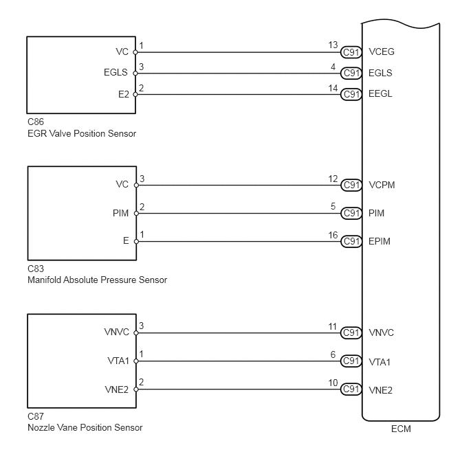
A227788E02
0.417,1.76 0.833,1.969 0.417,0.208 10 false C86 0.417,1.938 2.219,2.146 1.802,0.208 10 false EGR Valve Position Sensor 0.417,3.99 0.76,4.188 0.344,0.198 10 false C83 0.417,4.156 2.698,4.365 2.281,0.208 10 false Manifold Absolute Pressure Sensor 0.417,6.229 0.76,6.417 0.344,0.188 10 false C87 0.417,6.396 2.281,6.583 1.865,0.188 10 false Nozzle Vane Position Sensor 2.115,2.625 2.271,2.802 0.156,0.177 10 false 3 2.115,3.052 2.271,3.229 0.156,0.177 10 false 2 2.115,3.469 2.271,3.646 0.156,0.177 10 false 1 2.104,4.854 2.26,5.031 0.156,0.177 10 false 3 2.104,5.708 2.26,5.885 0.156,0.177 10 false 2 2.104,5.281 2.26,5.458 0.156,0.177 10 false 1 1.76,2.708 1.979,2.896 0.219,0.188 10 false VC 1.708,3.146 1.979,3.333 0.271,0.188 10 false PIM 1.865,3.563 2.021,3.74 0.156,0.177 10 false E 5.594,2.719 6.021,2.917 0.427,0.198 10 false VCPM 5.583,3.146 5.844,3.323 0.26,0.177 10 false PIM 5.583,3.573 5.938,3.75 0.354,0.177 10 false EPIM 1.573,1.01 1.969,1.188 0.396,0.177 10 false EGLS 1.792,1.344 1.979,1.521 0.188,0.177 10 false E2 1.76,0.698 1.969,0.875 0.208,0.177 10 false VC 2.104,0.604 2.26,0.781 0.156,0.177 10 false 1 2.104,1.25 2.26,1.427 0.156,0.177 10 false 2 2.104,0.927 2.26,1.104 0.156,0.177 10 false 3 4.969,0.594 5.135,0.771 0.167,0.177 10 false 13 4.969,1.25 5.135,1.427 0.167,0.177 10 false 14 5.01,0.927 5.167,1.104 0.156,0.177 10 false 4 5.198,0.708 5.469,0.885 0.271,0.177 10 false C91 5.208,1.021 5.479,1.198 0.271,0.177 10 false C91 5.208,1.344 5.479,1.521 0.271,0.177 10 false C91 5.198,5.813 5.469,5.99 0.271,0.177 10 false C91 5.198,4.958 5.469,5.135 0.271,0.177 10 false C91 5.198,5.385 5.469,5.563 0.271,0.177 10 false C91 5.208,3.573 5.479,3.75 0.271,0.177 10 false C91 5.208,3.146 5.479,3.323 0.271,0.177 10 false C91 5.208,2.719 5.479,2.896 0.271,0.177 10 false C91 4.969,2.625 5.198,2.844 0.229,0.219 10 false 12 4.969,3.479 5.135,3.656 0.167,0.177 10 false 16 5.01,3.042 5.167,3.219 0.156,0.177 10 false 5 4.969,4.865 5.135,5.042 0.167,0.177 10 false 11 4.969,5.719 5.135,5.896 0.167,0.177 10 false 10 5.01,5.292 5.167,5.469 0.156,0.177 10 false 6 5.594,4.958 6,5.146 0.406,0.188 10 false VNVC 5.594,5.406 6.021,5.583 0.427,0.177 10 false VTA1 5.594,5.833 5.969,6.01 0.375,0.177 10 false VNE2 5.594,0.698 6,0.885 0.406,0.188 10 false VCEG 5.583,1.021 5.969,1.198 0.385,0.177 10 false EGLS 5.583,1.333 5.969,1.51 0.385,0.177 10 false EEGL 1.583,4.948 1.99,5.135 0.406,0.188 10 false VNVC 1.635,5.385 2.042,5.563 0.406,0.177 10 false VTA1 1.594,5.823 1.969,6 0.375,0.177 10 false VNE2 5.927,6.417 6.333,6.656 0.406,0.24 10 false ECM

CAUTION / NOTICE / HINT

NOTICE:
·

Inspect the fuses for circuits related to this system before performing the following inspection procedure.

·

After replacing the ECM, the new ECM needs registration (See page Engine / Hybrid System>1KD-FTV (ENGINE CONTROL)>ECD SYSTEM>REGISTRATION) and initialization (See page Engine / Hybrid System>1KD-FTV (ENGINE CONTROL)>ECD SYSTEM>INITIALIZATION).


PROCEDURE

1.CHECK COMMUNICATION BETWEEN INTELLIGENT TESTER AND ECM
a.

Connect the intelligent tester to the DLC3.


b.

Turn the ignition switch to ON and tester on.


c.

Check the communication between the tester and ECM.

Result
Result Proceed to
Communication is possible A
Communication is not possible B


B

2.CHECK TERMINAL VOLTAGE (POWER SOURCE OF ECM)

A

PROCEED TO NEXT SUSPECTED AREA SHOWN IN PROBLEM SYMPTOMS TABLE

2.CHECK TERMINAL VOLTAGE (POWER SOURCE OF ECM)
a.

Turn the ignition switch to ON.


b.

Measure the voltage according to the value(s) in the table below.
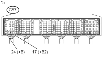

U169105E03
0.188,1.083 0.552,1.615 true 0.208,0.99 1.25,1.625 true 0.292,0.24 0.615,0.417 0.323,0.177 10 false G57 0.031,0 0.26,0.177 0.229,0.177 10 false *a 0.375,1.635 1.125,1.865 0.75,0.229 10 false 24 (+B) 1.073,1.635 1.823,1.865 0.75,0.229 10 false 17 (+B2)

Standard Voltage:
Tester Connection Switch Condition Specified Condition
G57-24 (+B) - Body ground Ignition switch ON 11 to 14 V
G57-17 (+B2) - Body ground Ignition switch ON 11 to 14 V


Text in Illustration
*a Component with harness connected (ECM)

HINT:

If the result is not as specified, since current is not flowing to the +B and +B2 terminals of the ECM, the system may not be started.


OK

3.CHECK CONNECTION BETWEEN INTELLIGENT TESTER AND ECM (ACCELERATOR PEDAL POSITION SENSOR)

NG

3.CHECK CONNECTION BETWEEN INTELLIGENT TESTER AND ECM (ACCELERATOR PEDAL POSITION SENSOR)
a.

Disconnect the accelerator pedal position sensor connector.


b.

Turn the ignition switch to ON.


c.

Turn the tester on.


d.

Check the communication between the intelligent tester and ECM.

Result
Result Proceed to
Communication is not possible A
Communication is possible B

HINT:

It can be checked using the "Engine" item of the Data List.


B

4.CHECK CONNECTION BETWEEN INTELLIGENT TESTER AND ECM (THROTTLE POSITION SENSOR)

A

REPLACE ACCELERATOR PEDAL ROD ASSEMBLY

4.CHECK CONNECTION BETWEEN INTELLIGENT TESTER AND ECM (THROTTLE POSITION SENSOR)
a.

Disconnect the throttle position sensor connector.


b.

Turn the ignition switch to ON.


c.

Turn the tester on.


d.

Check the communication between the intelligent tester and ECM.

Result
Result Proceed to
Communication is not possible A
Communication is possible B


B

5.CHECK CONNECTION BETWEEN INTELLIGENT TESTER AND ECM (FUEL PRESSURE SENSOR)

A

5.CHECK CONNECTION BETWEEN INTELLIGENT TESTER AND ECM (FUEL PRESSURE SENSOR)
a.

Disconnect the fuel pressure sensor connector.


b.

Turn the ignition switch to ON.


c.

Turn the tester on.


d.

Check the communication between the intelligent tester and ECM.

Result
Result Proceed to
Communication is not possible A
Communication is possible B

HINT:

It can be checked using the "Engine" item of the Data List.


B

6.CHECK CONNECTION BETWEEN INTELLIGENT TESTER AND ECM (EGR VALVE POSITION SENSOR)

A

6.CHECK CONNECTION BETWEEN INTELLIGENT TESTER AND ECM (EGR VALVE POSITION SENSOR)
a.

Disconnect the EGR valve position sensor connector.


b.

Turn the ignition switch to ON.


c.

Turn the tester on.


d.

Check the communication between the intelligent tester and ECM.

Result
Result Proceed to
Communication is not possible A
Communication is possible B

HINT:

It can be checked using the "Engine" item of the Data List.


B

7.CHECK CONNECTION BETWEEN INTELLIGENT TESTER AND ECM (MANIFOLD ABSOLUTE PRESSURE SENSOR)

A

REPLACE ELECTRIC EGR CONTROL VALVE ASSEMBLY

7.CHECK CONNECTION BETWEEN INTELLIGENT TESTER AND ECM (MANIFOLD ABSOLUTE PRESSURE SENSOR)
a.

Disconnect the manifold absolute pressure sensor connector.


b.

Turn the ignition switch to ON.


c.

Turn the tester on.


d.

Check the communication between the intelligent tester and ECM.

Result
Result Proceed to
Communication is not possible A
Communication is possible B

HINT:

It can be checked using the "Engine" item of the Data List.


B

8.CHECK CONNECTION BETWEEN INTELLIGENT TESTER AND ECM (NOZZLE VANE POSITION SENSOR)

A

8.CHECK CONNECTION BETWEEN INTELLIGENT TESTER AND ECM (NOZZLE VANE POSITION SENSOR)
a.

Disconnect the nozzle vane position sensor connector.


b.

Turn the ignition switch to ON.


c.

Turn the tester on.


d.

Check the communication between the intelligent tester and ECM.

Result
Result Proceed to
Communication is not possible A
Communication is possible B

HINT:

It can be checked using the "Engine" item of the Data List.


B

9.CHECK HARNESS AND CONNECTOR

A

9.CHECK HARNESS AND CONNECTOR
a.

Disconnect the accelerator pedal position sensor connector.


b.

Disconnect the throttle position sensor connector.


c.

Disconnect the fuel pressure sensor connector.


d.

Disconnect the EGR position sensor connector.


e.

Disconnect the nozzle vane position sensor connector.


f.

Disconnect the manifold absolute pressure sensor connector.


g.

Disconnect the ECM connectors.


h.

Measure the resistance according to the value(s) in the table below.

Standard Resistance:
Tester Connection Condition Specified Condition
G58-6 (VCPA) - Body ground Always 10 kΩ or higher
G58-4 (VCP2) - Body ground Always 10 kΩ or higher
C91-8 (VCVL) - Body ground Always 10 kΩ or higher
C90-14 (VCM) - Body ground Always 10 kΩ or higher
C90-13 (VCS) - Body ground Always 10 kΩ or higher
C91-13 (VCEG) - Body ground Always 10 kΩ or higher
C91-12 (VCPM) - Body ground Always 10 kΩ or higher
C91-11 (VNVC) - Body ground Always 10 kΩ or higher
G57-24 (+B) - Body ground Always 10 kΩ or higher
G57-17 (+B2) - Body ground Always 10 kΩ or higher


i.

Reconnect the accelerator pedal position sensor connector.


j.

Reconnect the throttle position sensor connector.


k.

Reconnect the fuel pressure sensor connector.


l.

Reconnect the EGR position sensor connector.


m.

Reconnect the nozzle vane position sensor connector.


n.

Reconnect the manifold absolute pressure sensor connector.


o.

Reconnect the ECM connectors.


OK

NG

REPAIR OR REPLACE HARNESS OR CONNECTOR