DOOR / HATCH REAR DOOR REASSEMBLY
CAUTION / NOTICE / HINT
- HINT:
- ·
Use the same procedure for RHD and LHD vehicles.
·The procedure listed below is for LHD vehicles.
·Use the same procedure for the RH and LH sides.
·The procedure listed below is for the LH side.
·A bolt without a torque specification is shown in the standard bolt chart (See page General>SPECIFICATIONS>STANDARD BOLT>SPECIFIED TORQUE FOR STANDARD BOLTS).
PROCEDURE

 1. REPAIR INSTRUCTION
75988E
2.INSTALL REAR DOOR OUTSIDE STRIPE LH
75928A
3.INSTALL BLACK OUT TAPE LH
75978H
4.INSTALL REAR DOOR LOWER OUTSIDE STRIPE LH
75924C
5.INSTALL NO. 2 BLACK OUT TAPE LH
75762A
6.INSTALL REAR DOOR FRONT WINDOW FRAME MOULDING LH
75722A
7.INSTALL REAR DOOR BELT MOULDING LH
67003C
8.INSTALL REAR DOOR PANEL CUSHION
Attach the clip to install a new door panel cushion.
67888A
9.INSTALL REAR DOOR NO. 2 WEATHERSTRIP LH
Attach the 6 clips and guide to install the rear door No. 2 weatherstrip.
67872
10.INSTALL REAR DOOR WEATHERSTRIP LH
Attach the 19 clips and guide to install the rear door weatherstrip.
68640A
11.INSTALL REAR DOOR CHECK ASSEMBLY LH
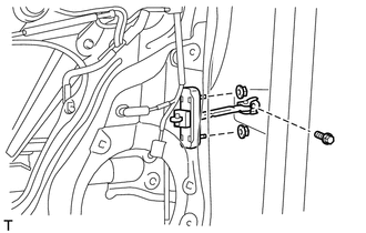
Install the door check to the door panel with the 2 nuts.
- Torque:
- 8.0 N*m (82 kgf*cm, 71 in.*lbf)
Apply adhesive to the threads of the bolt.
- Adhesive:
Toyota Genuine Adhesive 1324, Three Bond 1324 or equivalent
Install the door check to the body panel with the bolt.
- Torque:
- 27 N*m (275 kgf*cm, 20 ft.*lbf)
69204A
12.INSTALL REAR DOOR OUTSIDE HANDLE FRAME SUB-ASSEMBLY LH
Apply MP grease to the sliding parts of the rear door outside handle frame sub-assembly.
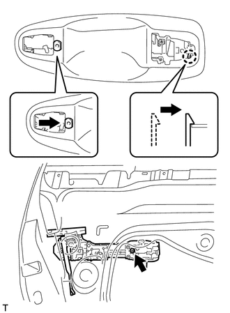
Attach the door handle nut and claw.
Using a T30 "TORX" socket wrench, install the rear door outside handle frame sub-assembly with the screw.
- Torque:
- 4.0 N*m (41 kgf*cm, 35 in.*lbf)
69254B
13.INSTALL REAR DOOR NO. 2 OUTSIDE HANDLE PAD LH
Attach the 2 claws to install the rear door No. 2 outside handle pad.
69252B
14.INSTALL REAR DOOR NO. 1 OUTSIDE HANDLE PAD LH
Attach the 3 claws to install the rear door No. 1 outside handle pad.
69240
15.INSTALL REAR DOOR OUTSIDE HANDLE ASSEMBLY LH
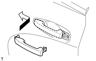
Insert the front end of the rear door outside handle assembly into the rear door outside handle frame.
- NOTICE:
-
If the bellcrank lever is not pulled and held when installing the outside handle, the bellcrank lever will interfere with the outside handle and the release plate will be damaged.
Insert the rear end of the rear door outside handle assembly into the rear door outside handle frame. Next, slide the rear door outside handle assembly toward the front of the vehicle to install it.
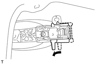
Move the lever in the direction indicated by the arrow in the illustration to lock the door outside handle assembly.
69227L
16.INSTALL REAR DOOR OUTSIDE HANDLE COVER LH
Attach the claw to install the rear door outside handle cover.
Using a T30 "TORX" socket wrench, install the rear door outside handle cover with the screw.
- Torque:
- 4.0 N*m (41 kgf*cm, 35 in.*lbf)
69780B
17.INSTALL REAR DOOR INSIDE LOCKING CABLE ASSEMBLY LH
Install the rear door inside locking cable assembly.
Attach the 3 claws.
69740D
18.INSTALL REAR DOOR LOCK REMOTE CONTROL CABLE ASSEMBLY LH
Install the rear door lock remote control cable assembly.
Attach the claw.
69340
19.INSTALL REAR DOOR LOCK ASSEMBLY LH
85710E
20.INSTALL REAR POWER WINDOW REGULATOR MOTOR ASSEMBLY LH
69840A
21.INSTALL REAR DOOR WINDOW REGULATOR ASSEMBLY LH
Apply MP grease to the sliding parts of the rear door window regulator assembly.
Install the temporary bolt to the rear door window regulator assembly.
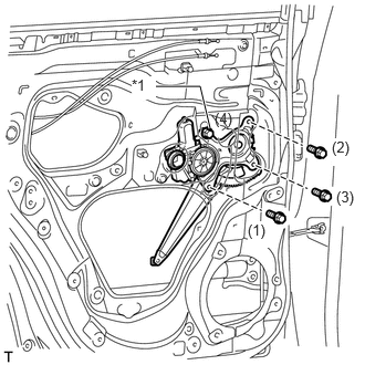
| *1 | Temporary Bolt |
Temporarily install the rear door window regulator assembly with the temporary bolt.
Temporarily install the 3 bolts, and then tighten the temporary bolt and 3 bolts.
- HINT:
-
Tighten the bolts in the order shown in the illustration.
- Torque:
- 8.0 N*m (82 kgf*cm, 71 in.*lbf)
69975A
22.INSTALL REAR DOOR GLASS CHANNEL FILLER
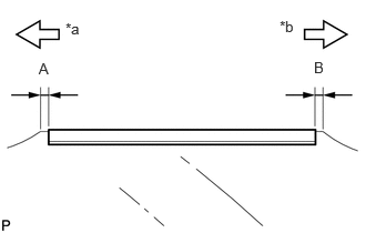
| *a | Front Side |
| *b | Rear Side |
Apply soapy water to a new rear door glass channel filler.
- Standard:
Area Specified Condition A 21 mm (0.827 in.) B 22.5 mm (0.886 in.)
Install the rear door glass channel filler to the position shown in the illustration.
69906B
23.INSTALL REAR DOOR GLASS CHANNEL SUB-ASSEMBLY LH
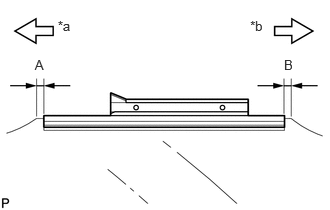
| *a | Front Side |
| *b | Rear Side |
Apply soapy water to a new rear door glass channel sub-assembly.
- Standard:
Area Specified Condition A 21 mm (0.827 in.) B 22.5 mm (0.886 in.)
- NOTICE:
-
To prevent damaging the rear door glass sub-assembly, be careful not to strike the channel with too much force.
Install the rear door glass channel sub-assembly to the position shown in the illustration.
68104
24.INSTALL REAR DOOR GLASS SUB-ASSEMBLY LH
Connect the cable to the negative (-) battery terminal and rear power window regulator motor connector.
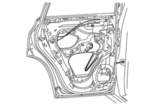
Connect the power window regulator switch assembly and move the arm of the regulator so that the roller on the arm can be seen through the service hole.
Disconnect the power window regulator switch assembly and rear power window regulator motor connector.
Disconnect the cable from the negative (-) battery terminal.
- CAUTION:
-
Wait at least 90 seconds after disconnecting the cable from the negative (-) battery terminal to disable the SRS system.
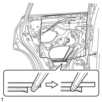
Insert the rear door glass sub-assembly into the rear door panel along the rear door glass run as indicated by the arrow in the illustration.
68189
25.INSTALL REAR DOOR QUARTER WINDOW WEATHERSTRIP LH
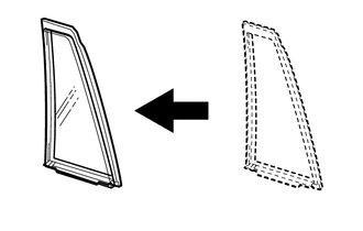
Install the rear door quarter window weatherstrip to the rear door quarter window glass.
68124B
26.INSTALL REAR DOOR QUARTER WINDOW GLASS LH
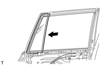
Install the rear door quarter window glass together with the rear door quarter window weatherstrip in the direction indicated by the arrow in the illustration.
67674A
27.INSTALL REAR DOOR FRAME GARNISH LH
Attach the clip to install a new door frame garnish.
67408E
28.INSTALL REAR DOOR WINDOW DIVISION BAR SUB-ASSEMBLY LH
Insert the rear door window division bar sub-assembly from above.
Install the rear door window division bar sub-assembly to the glass run.
Install the temporary bolt to the rear door window division bar sub-assembly.
Install the rear door window division bar sub-assembly.
Install the 2 bolts and screw.
Tighten the temporary bolt to install the rear door window division bar sub-assembly.
68152C
29.INSTALL REAR DOOR GLASS RUN LH
Install the glass run.
67842E
30.INSTALL REAR DOOR SERVICE HOLE COVER
Apply new butyl tape to the rear door panel.
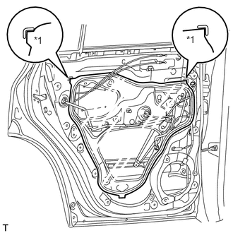
| *1 | Reference Point |
Pass the rear door lock remote control cable assembly and rear door inside locking cable assembly through a new rear door service hole cover.
Attach the rear door service hole cover using to the reference points on the rear door panel.
- NOTICE:
- ·
There should be no wrinkles or folds after attaching the service hole cover.
·After attaching the service hole cover, check the seal quality.
Connect the connector.
Attach the 2 clamps to the rear door wire.
86160C
31.INSTALL REAR SPEAKER SET
69206C
32.INSTALL REAR DOOR INSIDE HANDLE SUB-ASSEMBLY LH
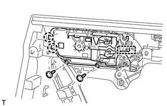
Attach the guide and 2 claws to install the rear door inside handle sub-assembly to the rear door trim board sub-assembly.
Install the 2 screws.
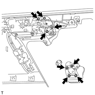
Install the 8 screws to the rear door armrest.
86160Y
33.INSTALL REAR NO. 2 SPEAKER ASSEMBLY (for 14 Speakers)
81081A
34.INSTALL NO. 2 INTERIOR ILLUMINATION LIGHT SUB-ASSEMBLY
81080G
35.INSTALL REAR DOOR INSIDE HANDLE ILLUMINATION LIGHT ASSEMBLY LH
81910D
36.INSTALL REAR REFLEX REFLECTOR ASSEMBLY
Attach the 2 claws to install the rear reflex reflector assembly.
84810D
37.INSTALL REAR POWER WINDOW REGULATOR SWITCH ASSEMBLY
68174A
38.INSTALL REAR DOOR INNER GLASS WEATHERSTRIP LH
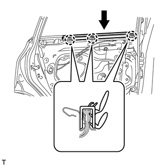
Attach the 3 claws to install the rear door inner glass weatherstrip as shown in the illustration.
67604
39.INSTALL REAR DOOR TRIM BOARD SUB-ASSEMBLY LH
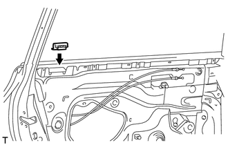
Install the clamp to the door panel.
Connect the rear door lock remote control cable assembly and rear door inside locking cable assembly.
Connect each connector.
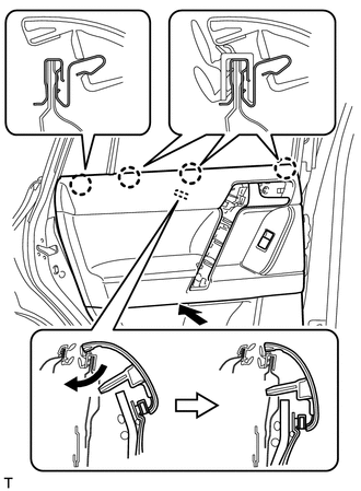
Attach the rear door trim board sub-assembly by attaching the 4 claws of the rear door inner glass weatherstrip as shown in the illustration.
Attach the 9 clips and install the rear door trim board sub-assembly.
Install the 3 screws.
74611C
40.INSTALL ASSIST GRIP COVER LH
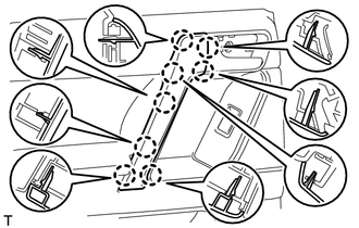
Attach the 8 claws to install the assist grip cover.
69298A
41.INSTALL NO. 2 DOOR INSIDE HANDLE BEZEL LH
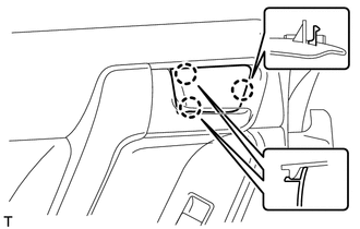
Attach the 3 claws to install the door inside handle bezel.
42.CONNECT CABLE TO NEGATIVE BATTERY TERMINAL
43. INITIALIZATION AFTER RECONNECTING BATTERY TERMINAL
Click hereGeneral>SETUP>WHEN DISCONNECTING OR RECONNECTING BATTERY TERMINAL>WORK PROCEDURE
- HINT:
-
When disconnecting and reconnecting the battery, there is an automatic learning function that completes learning when the respective system is used.
-
Click hereGeneral>SETUP>WHEN DISCONNECTING OR RECONNECTING BATTERY TERMINAL>AUTOMATIC LEARNING CHART