Home › Engine / Hybrid System › STOP AND START › STOP AND START SYSTEM › from 2020.08
RM27T0E _51 Engine / Hybrid System _091546 STOP AND START _0437376 STOP AND START SYSTEM J

STOP AND START  STOP AND START SYSTEM  Starter Signal Circuit  


DESCRIPTION

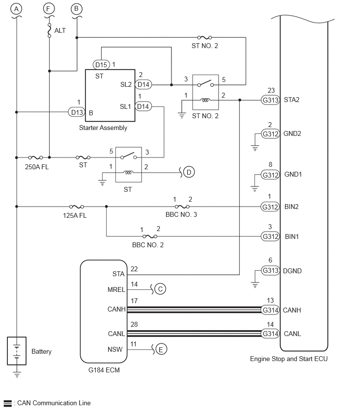
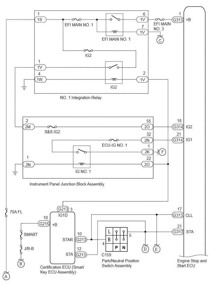
By using the starter delay circuit, the engine stop and start ECU can activate the ST NO. 2 relay (for starter motor operation) after activating the ST relay (for starter pinion operation) to operate the starter assembly.

WIRING DIAGRAM
A473898E01
6.344,0.583 6.656,0.781 0.313,0.198 10 false +B 5.906,0.594 6.521,0.792 0.615,0.198 10 false G313 6.104,0.385 6.26,0.583 0.156,0.198 10 false 1 4.781,0.583 5.094,0.781 0.313,0.198 10 false 1V 4.885,0.396 5.042,0.594 0.156,0.198 10 false 6 1.271,0.583 1.583,0.781 0.313,0.198 10 false 1S 1.281,0.385 1.438,0.583 0.156,0.198 10 false 1 1.25,2.625 1.563,2.823 0.313,0.198 10 false 1W 1.302,2.427 1.458,2.625 0.156,0.198 10 false 4 4.771,1.021 5.083,1.219 0.313,0.198 10 false 1V 4.833,0.823 4.99,1.021 0.156,0.198 10 false 7 5.24,0.729 5.906,1.063 0.667,0.333 10 false EFI MAIN NO. 3 2.208,0.76 4.354,0.958 2.146,0.198 10 false EFI MAIN NO. 1 3.479,1.25 5.625,1.448 2.146,0.198 10 false EFI MAIN NO. 1 5.417,1.302 5.573,1.5 0.156,0.198 10 false C 5.917,4.24 6.531,4.438 0.615,0.198 10 false G314 6.344,4.24 6.802,4.438 0.458,0.198 10 false IG2 6.344,4.677 6.802,4.875 0.458,0.198 10 false IG1 6.042,4.031 6.354,4.229 0.313,0.198 10 false 18 4.927,4.24 5.24,4.438 0.313,0.198 10 false 2O 5,4.042 5.313,4.24 0.313,0.198 10 false 55 1.521,4.406 2.594,4.604 1.073,0.198 10 false S&S IG2 0.854,4.24 1.167,4.438 0.313,0.198 10 false 2M 0.885,4.031 1.042,4.229 0.156,0.198 10 false 2 1.271,2.208 1.583,2.406 0.313,0.198 10 false 1V 1.302,2.01 1.458,2.208 0.156,0.198 10 false 1 3.771,2.885 4.229,3.083 0.458,0.198 10 false IG2 2.906,1.802 3.365,2 0.458,0.198 10 false IG2 4.781,2.635 5.094,2.833 0.313,0.198 10 false 1V 4.885,2.406 5.042,2.604 0.156,0.198 10 false 2 5.906,4.688 6.521,4.885 0.615,0.198 10 false G314 6.031,4.49 6.344,4.688 0.313,0.198 10 false 21 4.927,4.698 5.24,4.896 0.313,0.198 10 false 2N 5,4.49 5.313,4.688 0.313,0.198 10 false 32 2.573,5.76 3.948,5.958 1.375,0.198 10 false IG NO. 1 4.938,5.094 5.25,5.292 0.313,0.198 10 false 2K 5.042,4.896 5.198,5.094 0.156,0.198 10 false 1 5.51,5.094 5.667,5.292 0.156,0.198 10 false F 0.875,5.531 1.188,5.729 0.313,0.198 10 false 2N 0.906,5.281 1.063,5.479 0.156,0.198 10 false 1 4.927,5.521 5.24,5.719 0.313,0.198 10 false 2O 5,5.313 5.313,5.51 0.313,0.198 10 false 22 1.01,6.188 7.125,6.385 6.115,0.198 10 false Instrument Panel Junction Block Assembly 0.333,7.135 1.25,7.333 0.917,0.198 10 false 70A FL 1.99,7.042 2.604,7.24 0.615,0.198 10 false G213 2.396,7.052 2.552,7.25 0.156,0.198 10 false 3 6.333,7.26 6.792,7.458 0.458,0.198 10 false CLL 5.906,7.25 6.521,7.448 0.615,0.198 10 false G313 6.052,7.042 6.365,7.24 0.313,0.198 10 false 17 6.354,7.813 6.813,8.01 0.458,0.198 10 false STA 5.917,7.813 6.531,8.01 0.615,0.198 10 false G313 6.052,7.625 6.365,7.823 0.313,0.198 10 false 21 6.052,8.802 7.156,9.146 1.104,0.344 10 false Engine Stop and Start ECU 4.906,8.406 5.063,8.604 0.156,0.198 10 false D 5.292,8.417 5.448,8.615 0.156,0.198 10 false E 4.406,7.938 4.563,8.135 0.156,0.198 10 false 5 3.49,8.219 3.646,8.417 0.156,0.198 10 false 4 2.604,8.083 3.219,8.281 0.615,0.198 10 false G213 2.635,7.885 2.948,8.083 0.313,0.198 10 false 10 2.594,8.604 3.208,8.802 0.615,0.198 10 false G213 2.625,8.396 2.938,8.594 0.313,0.198 10 false 12 2.135,8.083 2.75,8.281 0.615,0.198 10 false STAR 2.24,8.583 2.698,8.781 0.458,0.198 10 false STA 1.781,7.573 2.094,7.771 0.313,0.198 10 false +B 1.344,7.542 1.958,7.74 0.615,0.198 10 false G215 1.479,7.333 1.698,7.521 0.219,0.188 10 false 10 0.813,7.906 1.583,8.104 0.771,0.198 10 false SMART 0.823,8.385 1.594,8.583 0.771,0.198 10 false J/B-B 0.156,9.344 0.313,9.542 0.156,0.198 10 false A 1.375,9.021 2.917,9.417 1.542,0.396 10 false Certification ECU (Smart Key ECU Assembly) 3.469,8.604 4.083,8.802 0.615,0.198 10 false C159 3.479,8.802 4.917,9.135 1.438,0.333 10 false Park/Neutral Position Switch Assembly 1.99,7.25 2.604,7.448 0.615,0.198 10 false IG1D 0.667,8.906 0.823,9.104 0.156,0.198 10 false B 3.479,4.865 5.313,5.063 1.833,0.198 10 false ECU-IG NO. 1 2.052,3.24 5.573,3.438 3.521,0.198 10 false NO. 1 Integration Relay

A475020E01
0.302,0.104 0.458,0.302 0.156,0.198 10 false A 1.573,0.094 1.729,0.292 0.156,0.198 10 false B 3.354,6.052 3.51,6.25 0.156,0.198 10 false C 3.958,3.573 4.115,3.771 0.156,0.198 10 false D 1.677,2.625 2.896,2.865 1.219,0.24 10 false Starter Assembly 1.885,2.313 2.042,2.51 0.156,0.198 10 false B 0.667,7.375 1.74,7.573 1.073,0.198 10 false Battery 2.542,2.177 3,2.375 0.458,0.198 10 false SL1 2.552,1.708 3.01,1.906 0.458,0.198 10 false SL2 2.021,1.531 2.292,1.729 0.271,0.198 10 false ST 4.073,2.375 4.792,2.594 0.719,0.219 10 false ST NO. 2 3.906,1.594 4.063,1.792 0.156,0.198 10 false 3 4.708,1.604 4.865,1.802 0.156,0.198 10 false 5 3.906,1.938 4.104,2.125 0.198,0.188 10 false 1 4.698,1.938 4.875,2.125 0.177,0.188 10 false 2 6.021,2.031 6.635,2.229 0.615,0.198 10 false STA2 5.573,2.042 6.031,2.24 0.458,0.198 10 false G313 5.677,1.833 5.99,2.031 0.313,0.198 10 false 23 4.063,0.885 5.292,1.083 1.229,0.198 10 false ST NO. 2 2.385,5.729 2.844,5.927 0.458,0.198 10 false STA 2.281,6.063 2.896,6.26 0.615,0.198 10 false MREL 2.281,6.479 2.896,6.677 0.615,0.198 10 false CANH 6,6.5 6.615,6.698 0.615,0.198 10 false CANH 2.292,7 2.906,7.198 0.615,0.198 10 false CANL 6.021,7 6.635,7.198 0.615,0.198 10 false CANL 2.281,7.333 2.74,7.531 0.458,0.198 10 false NSW 3.365,7.344 3.521,7.542 0.156,0.198 10 false E 0.292,8.469 3.958,8.667 3.667,0.198 10 false : CAN Communication Line 2.24,7.771 2.698,7.969 0.458,0.198 10 false ECM 5.302,7.531 7.042,7.771 1.74,0.24 10 false Engine Stop and Start ECU 6.031,3.615 6.646,3.813 0.615,0.198 10 false GND1 6.01,2.75 6.625,2.948 0.615,0.198 10 false GND2 6,5.667 6.615,5.865 0.615,0.198 10 false DGND 5.573,5.656 6.031,5.854 0.458,0.198 10 false G313 5.698,5.438 5.854,5.635 0.156,0.198 10 false 6 5.573,2.76 6.031,2.958 0.458,0.198 10 false G312 5.698,3.406 5.854,3.604 0.156,0.198 10 false 8 5.573,3.635 6.031,3.833 0.458,0.198 10 false G312 5.688,2.563 5.844,2.76 0.156,0.198 10 false 2 5.573,6.5 6.031,6.698 0.458,0.198 10 false G314 5.656,6.292 5.969,6.49 0.313,0.198 10 false 13 5.573,7 6.031,7.198 0.458,0.198 10 false G314 5.656,6.802 5.969,7 0.313,0.198 10 false 14 2.625,3.938 3.344,4.156 0.719,0.219 10 false ST 1.677,3.417 2.396,3.635 0.719,0.219 10 false ST 1.156,0.563 1.615,0.76 0.458,0.198 10 false ALT 5.573,4.938 6.031,5.135 0.458,0.198 10 false G312 5.563,4.313 6.021,4.51 0.458,0.198 10 false G312 6.042,4.938 6.656,5.135 0.615,0.198 10 false BIN1 5.688,4.729 5.844,4.927 0.156,0.198 10 false 3 6.031,4.302 6.646,4.5 0.615,0.198 10 false BIN2 5.677,4.083 5.854,4.26 0.177,0.177 10 false 1 3.51,4.469 4.333,4.677 0.823,0.208 10 false BBC NO. 3 2.802,5.115 3.625,5.323 0.823,0.208 10 false BBC NO. 2 2.313,3.448 2.458,3.76 0.146,0.313 10 false 1 3.083,3.146 3.24,3.344 0.156,0.198 10 false 3 2.323,3.125 2.479,3.323 0.156,0.198 10 false 5 3.063,3.458 3.24,3.646 0.177,0.188 10 false 2 2.021,1.292 2.479,1.49 0.458,0.198 10 false D15 2.375,1.281 2.573,1.469 0.198,0.188 10 false 1 2.917,1.708 3.375,1.906 0.458,0.198 10 false D14 2.948,1.5 3.125,1.688 0.177,0.188 10 false 2 2.906,2.177 3.365,2.375 0.458,0.198 10 false D14 2.927,1.958 3.125,2.146 0.198,0.188 10 false 1 1.51,2.302 1.969,2.5 0.458,0.198 10 false D13 1.635,2.083 1.833,2.271 0.198,0.188 10 false 1 0.531,3.458 1.604,3.656 1.073,0.198 10 false 250A FL 2.771,5.625 3.083,5.823 0.313,0.198 10 false 22 2.771,5.948 3.083,6.146 0.313,0.198 10 false 14 2.771,6.302 3.083,6.5 0.313,0.198 10 false 17 2.771,6.802 3.083,7 0.313,0.198 10 false 28 2.76,7.219 3.073,7.417 0.313,0.198 10 false 11 1.875,7.771 2.333,7.969 0.458,0.198 10 false G184 3.667,4.146 3.823,4.344 0.156,0.198 10 false 1 4,4.146 4.156,4.344 0.156,0.198 10 false 2 2.969,4.792 3.125,4.99 0.156,0.198 10 false 1 3.323,4.771 3.479,4.969 0.156,0.198 10 false 2 1.333,4.49 2.406,4.688 1.073,0.198 10 false 125A FL 0.979,0.104 1.135,0.302 0.156,0.198 10 false F

CAUTION / NOTICE / HINT

NOTICE:
·

Before replacing the engine stop and start ECU, read the number of starter operations and write it into a new engine stop and start ECU.

Click hereEngine / Hybrid System>STOP AND START>STOP AND START SYSTEM>REGISTRATION

·

After replacing the engine stop and start ECU or air conditioning amplifier assembly, reset and perform learning of the air conditioning information in the engine stop and start ECU.

Click hereEngine / Hybrid System>STOP AND START>STOP AND START SYSTEM>REGISTRATION

·

After replacing the engine stop and start ECU, airbag sensor assembly, clear and calibrate the deceleration sensor zero point in the engine stop and start ECU.

Click hereEngine / Hybrid System>STOP AND START>STOP AND START SYSTEM>REGISTRATION

·

After replacing the starter assembly, perform initialization of the number of starter operations stored in the engine stop and start ECU.

Click hereEngine / Hybrid System>STOP AND START>STOP AND START SYSTEM>REGISTRATION

·

After replacing the engine stop and start ECU assembly, perform learning of the external backup boost converter (eco run vehicle converter assembly).

Click hereEngine / Hybrid System>STOP AND START>STOP AND START SYSTEM>REGISTRATION

·

When the starter assembly is replaced, "ST relay" and "ST NO. 2 relay" must be also replaced.

·

Inspect the fuses for circuits related to this system before performing the following procedure.

·

After replacing the engine stop and start ECU, perform learning of the external backup boost converter (eco run vehicle converter assembly).

Click hereGeneral>INTRODUCTION>REPAIR INSTRUCTION>PRECAUTION

·

When disconnecting and reconnecting the battery.

Click hereGeneral>SETUP>WHEN REPLACING OR REMOVING/INSTALLING PARTS>WORK PROCEDURE

HINT:

When disconnecting and reconnecting the battery, there is an automatic learning function that completes learning when the respective system is used.

Click hereGeneral>SETUP>WHEN DISCONNECTING OR RECONNECTING BATTERY TERMINAL>AUTOMATIC LEARNING CHART


·

When the engine stop and start ECU or electromagnetic oil pump is replaced, check the electromagnetic oil pump.

Click hereEngine / Hybrid System>STOP AND START>STOP AND START SYSTEM>REGISTRATION


PROCEDURE

1.CHECK CRANKING
a.

Turn the engine switch on (START) and check that the engine cranks.


Result:
Result Proceed to
Engine cranks A
Engine does not crank B


A

2.PERFORM ACTIVE TEST USING GTS (STARTER(HOOD CLOSE))

B

5.PERFORM ACTIVE TEST USING GTS (STARTER(HOOD CLOSE))
2.PERFORM ACTIVE TEST USING GTS (STARTER(HOOD CLOSE))
a.

Connect the GTS to the DLC3.


b.

Turn the engine switch on (IG).


c.

Turn the GTS on.


d.

Enter the following menus: Powertrain / Stop and Start / Active Test / Starter(Hood Close).


e.

Check whether the engine cranks while the Active Test "Starter" is being performed.

NOTICE:

The Active Test "Starter" is stopped automatically 3 seconds after the starter assembly begins operating.


Standard:

Engine cranks


Result:
Proceed to
OK
NG


OK

GO TO DTC P160300 (CONFIRM CAUSE OF ENGINE STALL)

NG

3.CHECK HARNESS AND CONNECTOR (ENGINE STOP AND START ECU POWER SOURCE CIRCUIT)
a.

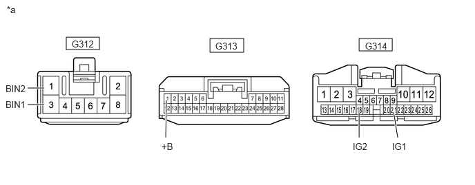
Disconnect the engine stop and start ECU connectors.
A346921C14
1,0.563 1.5,0.75 0.5,0.188 3.167,0.583 3.677,0.792 0.51,0.208 5.417,0.583 5.917,0.771 0.5,0.188 0.667,1.333 0.417,1.333 true 0.667,1.583 0.417,1.583 true 2.51,1.521 2.5,2.083 true 5.938,1.698 6,2.083 true 5.417,1.708 5.417,2.083 true 1.083,0.583 1.542,0.781 0.458,0.198 10 false G312 3.25,0.615 3.708,0.813 0.458,0.198 10 false G313 5.51,0.615 5.969,0.813 0.458,0.198 10 false G314 0.104,0.063 0.417,0.26 0.313,0.198 10 false *a 0.083,1.26 0.698,1.458 0.615,0.198 10 false BIN2 0.083,1.5 0.698,1.698 0.615,0.198 10 false BIN1 2.438,2.135 2.75,2.333 0.313,0.198 10 false +B 5.917,2.135 6.375,2.333 0.458,0.198 10 false IG1 5.323,2.135 5.781,2.333 0.458,0.198 10 false IG2
*a Front view of wire harness connector
(to Engine Stop and Start ECU)
- -


b.

Measure the voltage according to the value(s) in the table below.

Standard Voltage:
Tester Connection Condition Specified Condition
G312-1 (BIN2) - Body ground Always 9.5 to 14 V
G312-3 (BIN1) - Body ground Always 9.5 to 14 V


c.

Turn the engine switch on (IG).


d.

Measure the voltage according to the value(s) in the table below.

Standard Voltage:
Tester Connection Condition Specified Condition
G313-1 (+B) - Body ground Engine switch on (IG) 9.5 to 14 V
G314-21 (IG1) - Body ground Engine switch on (IG) 9.5 to 14 V
G314-18 (IG2) - Body ground Engine switch on (IG) 9.5 to 14 V


Result:
Proceed to
OK
NG


OK

4.CHECK HARNESS AND CONNECTOR (ENGINE STOP AND START ECU - BODY GROUND)

NG

REPAIR OR REPLACE HARNESS OR CONNECTOR

4.CHECK HARNESS AND CONNECTOR (ENGINE STOP AND START ECU - BODY GROUND)
a.

Disconnect the engine stop and start ECU connectors.


b.

Measure the resistance according to the value(s) in the table below.

Standard Resistance:
Tester Connection Condition Specified Condition
G312-2 (GND2) - Body ground Always Below 1 Ω
G312-8 (GND1) - Body ground Always Below 1 Ω
G313-6 (DGND) - Body ground Always Below 1 Ω


Result:
Proceed to
OK
NG


OK

NG

REPAIR OR REPLACE HARNESS OR CONNECTOR

5.PERFORM ACTIVE TEST USING GTS (STARTER(HOOD CLOSE))
a.

Connect the GTS to the DLC3.


b.

Turn the engine switch on (IG).


c.

Turn the GTS on.


d.

Enter the following menus: Powertrain / Stop and Start / Active Test / Starter(Hood Close).


e.

Check whether the engine cranks while the Active Test "Starter" is being performed.

NOTICE:

The Active Test "Starter" is stopped automatically 3 seconds after the starter assembly begins operating.


Standard:

Engine cranks


Result:
Result Proceed to
Engine cranks A
Engine does not crank B


A

6.READ VALUE USING GTS (NEUTRAL SWITCH)

B

11.CHECK ENGINE STOP AND START ECU (STA, STA2 SIGNAL)
6.READ VALUE USING GTS (NEUTRAL SWITCH)
a.

Connect the GTS to the DLC3.


b.

Turn the engine switch on (IG).


c.

Turn the GTS on.


d.

Enter the following menus: Powertrain / Stop and Start / Data List / Neutral Switch.


e.

In accordance with the display on the GTS, read the Data List.

OK:
Tester Display Condition Normal Condition
Neutral Switch Shift lever in P or N ON
Shift lever not in P or N OFF


Result:
Proceed to
OK
NG


OK

7.CHECK HARNESS AND CONNECTOR (CERTIFICATION ECU (SMART KEY ECU ASSEMBLY) - ENGINE STOP AND START ECU)

NG

9.INSPECT PARK/NEUTRAL POSITION SWITCH ASSEMBLY
7.CHECK HARNESS AND CONNECTOR (CERTIFICATION ECU (SMART KEY ECU ASSEMBLY) - ENGINE STOP AND START ECU)
a.

Disconnect the park/neutral position switch assembly connector.


b.

Disconnect the certification ECU (smart key ECU assembly) connector.


c.

Disconnect the engine stop and start ECU connector.


d.

Measure the resistance according to the value(s) in the table below.

Standard Resistance:
Tester Connection Condition Specified Condition
G213-10 (STAR) - G313-17 (CLL) Always Below 1 Ω
G213-10 (STAR) - Body ground Always 10 kΩ or higher
G313-17 (CLL) - Body ground Always 10 kΩ or higher


Result:
Proceed to
OK
NG


OK

8.CHECK CERTIFICATION ECU (SMART KEY ECU ASSEMBLY) (STAR SIGNAL)

NG

REPAIR OR REPLACE HARNESS OR CONNECTOR

8.CHECK CERTIFICATION ECU (SMART KEY ECU ASSEMBLY) (STAR SIGNAL)
a.
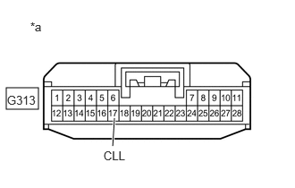
A288763C64
0.073,1.021 0.448,1.271 0.375,0.25 1.313,1.698 1.333,1.375 true 0.354,0.229 0.667,0.385 0.313,0.156 10 false *a 1.208,1.729 1.667,1.927 0.458,0.198 10 false CLL 0.083,1.083 0.542,1.281 0.458,0.198 10 false G313
*a Front view of wire harness connector
(to Engine Stop and Start ECU)


Disconnect the engine stop and start ECU connector.


b.

Measure the voltage according to the value(s) in the table below.

Standard Voltage:
Tester Connection Condition Specified Condition
G313-17 (CLL) - Body ground Engine started using engine switch (engine switch turned on (START)) 9.5 to 14 V


Result:
Proceed to
OK
NG


OK

PROCEED TO NEXT SUSPECTED AREA SHOWN IN PROBLEM SYMPTOMS TABLE

NG

9.INSPECT PARK/NEUTRAL POSITION SWITCH ASSEMBLY
a.

Result:
Proceed to
OK
NG


OK

10.CHECK HARNESS AND CONNECTOR (CERTIFICATION ECU (SMART KEY ECU ASSEMBLY) - ST RELAY)

NG

10.CHECK HARNESS AND CONNECTOR (CERTIFICATION ECU (SMART KEY ECU ASSEMBLY) - ST RELAY)
a.

Disconnect the certification ECU (smart key ECU assembly) connector.


b.

Remove the ST relay from the engine room relay block and junction block assembly.


c.

Measure the resistance according to the value(s) in the table below.

Standard Resistance:
Tester Connection Condition Specified Condition
G213-10 (STAR) - ST relay terminal 2 Shift lever in P or N Below 1 Ω
Shift lever not in P or N 10 kΩ or higher


Result:
Proceed to
OK
NG


OK

PROCEED TO NEXT SUSPECTED AREA SHOWN IN PROBLEM SYMPTOMS TABLE

NG

REPAIR OR REPLACE HARNESS OR CONNECTOR

11.CHECK ENGINE STOP AND START ECU (STA, STA2 SIGNAL)
a.

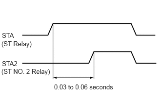
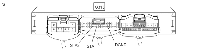
Connect an oscilloscope to the STA, STA2 and DGND terminals of the engine stop and start ECUconnector.
A456121C51
3.26,0.094 3.646,0.365 0.385,0.271 3.698,0.823 3.969,1.438 true 3.219,0.927 2.76,1.49 true 3.365,0.927 3.198,1.49 true 0.052,0.063 0.365,0.26 0.313,0.198 10 false *a 4,1.49 4.615,1.688 0.615,0.198 10 false DGND 2.438,1.51 3.052,1.708 0.615,0.198 10 false STA2 3.302,0.167 3.917,0.365 0.615,0.198 10 false G313 3.021,1.542 3.635,1.74 0.615,0.198 10 false STA
*a Component with harness connected
(Engine Stop and Start ECU)
- -


b.
A285702E50
0.042,0.677 0.5,0.875 0.458,0.198 10 false STA 0.042,1.281 0.5,1.479 0.458,0.198 10 false STA2 1.156,1.781 3.146,1.979 1.99,0.198 10 false 0.03 to 0.06 seconds 0.031,0.854 1.865,1.052 1.833,0.198 10 false (ST Relay) 0.031,1.448 1.865,1.646 1.833,0.198 10 false (ST NO. 2 Relay)

Check the waveform immediately after turning the engine switch on (START).

Item Condition
Tester Connection G313-21 (STA) - G313-6 (DGND)
G313-23 (STA2) - G313-6 (DGND)
Condition Engine started by engine switch operation

Result:
Result Proceed to
Delay between ST relay turning on and ST NO. 2 relay turning on: between 0.03 and 0.06 seconds A
Delay between ST relay turning on and ST NO. 2 relay turning on: not between 0.03 and 0.06 seconds B
ST relay turns on and ST NO. 2 relay does not turn on C
ST relay and ST NO. 2 relay do not turn on D


NOTICE:

After replacing the engine stop and start ECU, make sure that the flywheel sub-assembly and starter pinion gear are not excessively worn. A malfunction in the delay circuit may cause the flywheel sub-assembly or starter pinion gear to be worn or damaged.


A

12.INSPECT RELAY (ST, ST NO. 2 RELAY)

B

C

3.CHECK HARNESS AND CONNECTOR (ENGINE STOP AND START ECU POWER SOURCE CIRCUIT)

D

15.CHECK HARNESS AND CONNECTOR (ST RELAY - BODY GROUND)
12.INSPECT RELAY (ST, ST NO. 2 RELAY)


Result:
Proceed to
OK
NG


OK

13.CHECK HARNESS AND CONNECTOR (ST, ST NO. 2 RELAY - BATTERY)

NG

REPLACE RELAY (ST, ST NO. 2 RELAY)

13.CHECK HARNESS AND CONNECTOR (ST, ST NO. 2 RELAY - BATTERY)
a.
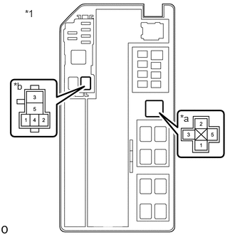
A475031C01
0.365,0.115 0.677,0.313 0.313,0.198 10 false *1 2.635,1.646 2.948,1.844 0.313,0.198 10 false *a 0.198,1.177 0.51,1.375 0.313,0.198 10 false *b
*1 Engine Room Relay Block and Junction Block Assembly
*a ST Relay Terminal
*b ST NO. 2 Relay Terminal


Remove the ST and ST NO. 2 relays from the engine room relay block and junction block assembly.


b.

Measure the voltage according to the value(s) in the table below.

Standard Voltage:
Tester Connection Condition Specified Condition
ST relay terminal 5 - Body ground Always 9.5 to 14 V
ST NO. 2 relay terminal 5 - Body ground Always 9.5 to 14 V


Result:
Proceed to
OK
NG


OK

14.CHECK HARNESS AND CONNECTOR (ST, ST NO. 2 RELAY - STARTER ASSEMBLY)

NG

REPAIR OR REPLACE HARNESS OR CONNECTOR

14.CHECK HARNESS AND CONNECTOR (ST, ST NO. 2 RELAY - STARTER ASSEMBLY)
a.

Remove the ST and ST NO. 2 relays from the engine room relay block and junction block assembly.


b.

Disconnect the starter assembly connector.


c.

Measure the resistance according to the value(s) in the table below.

Standard Resistance:
Tester Connection Condition Specified Condition
ST relay terminal 3 - D14-1 (SL1) Always Below 1 Ω
ST NO. 2 relay terminal 3 - D14-2 (SL2) Always Below 1 Ω
ST NO. 2 relay terminal 3 - D15-1 (ST) Always Below 1 Ω


Result:
Proceed to
OK
NG


OK

15.CHECK HARNESS AND CONNECTOR (ST RELAY - BODY GROUND)

NG

REPAIR OR REPLACE HARNESS OR CONNECTOR

15.CHECK HARNESS AND CONNECTOR (ST RELAY - BODY GROUND)
a.

Remove the ST relay from the engine room relay block and junction block assembly.


b.

Measure the resistance according to the value(s) in the table below.

Standard Resistance:
Tester Connection Condition Specified Condition
ST relay terminal 1 - Body ground Always Below 1 Ω


Result:
Proceed to
OK
NG


OK

16.CHECK HARNESS AND CONNECTOR (ST NO. 2 RELAY - BODY GROUND)

NG

REPAIR OR REPLACE HARNESS OR CONNECTOR

16.CHECK HARNESS AND CONNECTOR (ST NO. 2 RELAY - BODY GROUND)
a.

Remove the ST NO. 2 relay from the engine room relay block and junction block assembly.


b.

Measure the resistance according to the value(s) in the table below.

Standard Resistance:
Tester Connection Condition Specified Condition
ST NO. 2 relay terminal 1 - Body ground Always Below 1 Ω


Result:
Proceed to
OK
NG


OK

17.CHECK HARNESS AND CONNECTOR (ENGINE STOP AND START ECU - ST RELAY)

NG

REPAIR OR REPLACE HARNESS OR CONNECTOR

17.CHECK HARNESS AND CONNECTOR (ENGINE STOP AND START ECU - ST RELAY)
a.

Disconnect the certification ECU (smart key ECU assembly) connector.


b.

Disconnect the park/neutral position switch assembly connector.


c.

Disconnect the engine stop and start ECU connector.


d.

Remove the ST relay from the engine room relay block and junction block.


e.

Measure the resistance according to the value(s) in the table below.

Standard Resistance:
Tester Connection Condition Specified Condition
G313-21 (STA) - ST relay terminal 2 Always Below 1 Ω
G313-21 (STA) - Body ground Always 10 kΩ or higher
ST relay terminal 2 - Body ground Always 10 kΩ or higher


Result:
Proceed to
OK
NG


OK

18.CHECK HARNESS AND CONNECTOR (ENGINE STOP AND START ECU - ST NO. 2 RELAY)

NG

REPAIR OR REPLACE HARNESS OR CONNECTOR

18.CHECK HARNESS AND CONNECTOR (ENGINE STOP AND START ECU - ST NO. 2 RELAY)
a.

Disconnect the ECM connector.


b.

Disconnect the engine stop and start ECU connector.


c.

Remove the ST NO. 2 relay from the engine room relay block and junction block assembly.


d.

Measure the resistance according to the value(s) in the table below.

Standard Resistance:
Tester Connection Condition Specified Condition
G313-23 (STA2) - ST NO. 2 relay terminal 2 Always Below 1 Ω
G313-23 (STA2) - Body ground Always 10 kΩ or higher
ST NO. 2 relay terminal 2 - Body ground Always 10 kΩ or higher


Result:
Proceed to
OK
NG


OK

19.CHECK STARTER SIGNAL (OUTPUT WAVEFORM)

NG

REPAIR OR REPLACE HARNESS OR CONNECTOR

19.CHECK STARTER SIGNAL (OUTPUT WAVEFORM)
a.

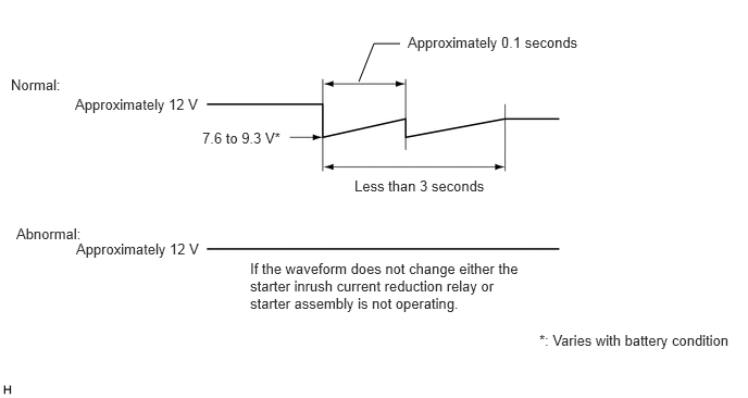
Connect the positive (+) lead of an oscilloscope to the positive (+) battery terminal and the negative (-) lead to the negative (-) battery terminal.


b.

While cranking the engine, count the number of times the waveform drops.
A285237E02
3.438,0.781 3.583,0.417 3.583,0.417 3.833,0.417 false 0.104,0.729 0.719,0.927 0.615,0.198 10 false Normal: 0.156,2.156 0.771,2.354 0.615,0.198 10 false Abnormal: 0.719,0.917 2.042,1.135 1.323,0.219 10 false Approximately 12 V 1.938,1.24 3.927,1.438 1.99,0.198 10 false 7.6 to 9.3 V* 3.906,0.323 5.667,0.542 1.76,0.219 10 false Approximately 0.1 seconds 3.396,1.698 5.073,1.896 1.677,0.198 10 false Less than 3 seconds 5.167,3.177 7.083,3.5 1.917,0.323 10 false *: Varies with battery condition 2.396,2.49 5.031,3.042 2.635,0.552 10 false If the waveform does not change either the starter inrush current reduction relay or starter assembly is not operating. 0.729,2.302 2.052,2.521 1.323,0.219 10 false Approximately 12 V

Standard:

Waveform drops 2 times


Result:
Number of Times Waveform Dropped Proceed to
0 times A
2 times B


A

B

20.INSPECT STARTER ASSEMBLY

Result:
Proceed to
OK
NG


OK

PROCEED TO NEXT SUSPECTED AREA SHOWN IN PROBLEM SYMPTOMS TABLE

NG