5L-E ENGINE MECHANICAL CAMSHAFT REMOVAL
PROCEDURE

 1.DISCONNECT CABLE FROM NEGATIVE BATTERY TERMINAL
53292A
2.REMOVE UPPER RADIATOR SUPPORT SEAL
52129B
3.REMOVE FRONT BUMPER COVER LOWER
51405A
4.REMOVE NO. 1 ENGINE UNDER COVER SUB-ASSEMBLY
5.DRAIN ENGINE COOLANT
53736
6.REMOVE FRONT FENDER APRON SEAL RH
7.REMOVE RESONATOR WITH AIR CLEANER CAP SUB-ASSEMBLY
17801
8.REMOVE AIR CLEANER FILTER ELEMENT SUB-ASSEMBLY
17700
9.REMOVE AIR CLEANER CASE ASSEMBLY
10.DISCONNECT WIRE HARNESS
Remove the terminal cap.
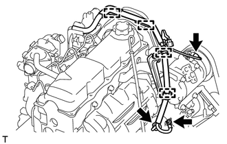
Remove the nut and generator wire.
Disconnect the generator connector and cooler compressor connector.
Detach the 4 wire harness clamps.
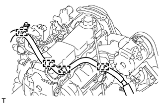
for LHD:
Detach the 4 wire harness clamps.
82715
11.REMOVE WIRING HARNESS CLAMP BRACKET (for LHD)
16571C
12.REMOVE NO. 1 RADIATOR HOSE
16470
13.REMOVE RADIATOR RESERVE TANK ASSEMBLY
16711
14.REMOVE FAN SHROUD
44319
15.REMOVE VANE PUMP DRIVE PULLEY
13471
16.REMOVE CRANKSHAFT PULLEY
88545
17.REMOVE IDLE PULLEY ASSEMBLY
11302
18.REMOVE TIMING BELT COVER
13566A
19.REMOVE TIMING BELT GUIDE
20.SET NO. 1 CYLINDER TO TDC/COMPRESSION
13568
21.REMOVE TIMING BELT
17130
22.REMOVE INTAKE PIPE
11201
23.REMOVE CYLINDER HEAD COVER SUB-ASSEMBLY
13523P
24.REMOVE CAMSHAFT TIMING PULLEY
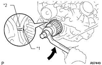
Using the crankshaft pulley bolt, turn the crankshaft 90° counterclockwise and align the timing mark of the crankshaft timing pulley with the protrusion of the timing belt case.

|
Turn |
| *1 | Timing Mark |
| *2 | Protrusion |
- HINT:
-
Set the No. 1 cylinder to 90° BTDC/compression to avoid interference with the piston top and valve head.
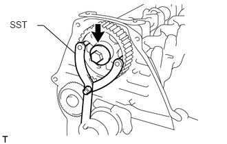
Using SST, loosen the pulley bolt.
- SST
- 09960-10010 (09962-01000, 09963-01000)
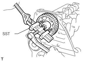
Using SST, separate the timing pulley from the camshaft.
- SST
- 09950-50013 (09951-05010, 09952-05010, 09953-05010, 09954-05021)
Remove the pulley bolt and timing pulley.
Remove the timing pulley woodruff key.
11322B
25.REMOVE NO. 2 TIMING BELT COVER
Remove the 4 bolts and timing belt cover.
11385
26.REMOVE CAMSHAFT OIL SEAL RETAINER
Remove the 4 bolts, retainer and gasket.
11305A
27.REMOVE CAMSHAFT OIL SEAL
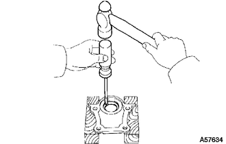
Using a screwdriver and hammer, tap out the oil seal.
13511
28.REMOVE CAMSHAFT
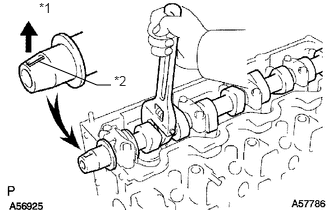
Turn the camshaft with a wrench so that the key groove faces upward.
| *1 | Upward |
| *2 | Key Groove |
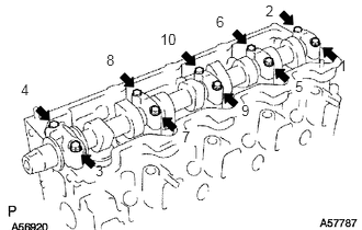
Uniformly loosen and remove the 10 bearing cap bolts in several steps in the sequence shown in the illustration.
Remove the 5 bearing caps and camshaft.
- HINT:
-
Arrange the bearing caps in the correct order.