BRAKE SYSTEM (OTHER) BRAKE PEDAL(for Vacuum Brake Booster) INSTALLATION
PROCEDURE

 55106
1.INSTALL BRAKE PEDAL SUPPORT SUB-ASSEMBLY
Temporarily install the set bolt.
for LHD:
Install the brake booster assembly (See page Brake>BRAKE SYSTEM (OTHER)>BRAKE BOOSTER>INSTALLATION).
Install the brake master cylinder sub-assembly (See page Brake>BRAKE SYSTEM (OTHER)>BRAKE MASTER CYLINDER>INSTALLATION).
for RHD:
Install the brake booster (See page Brake>BRAKE SYSTEM (OTHER)>BRAKE BOOSTER>INSTALLATION).
Install the brake master cylinder sub-assembly (See page Brake>BRAKE SYSTEM (OTHER)>BRAKE MASTER CYLINDER>INSTALLATION).
Install the brake actuator assembly (See page Brake>BRAKE CONTROL / DYNAMIC CONTROL SYSTEMS>BRAKE ACTUATOR>INSTALLATION).
Install the brake pedal support sub-assembly with the 4 nuts.
- Torque:
- 14 N*m (145 kgf*cm, 10 ft.*lbf)
Install the brake pedal support reinforcement set bolt.
- Torque:
- 20 N*m (204 kgf*cm, 15 ft.*lbf)
47264A
2.INSTALL PUSH ROD PIN
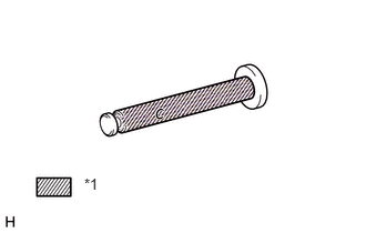
Apply a light coat of lithium soap base glycol grease to the inner surface of the hole on the brake pedal lever.
| *1 | Lithium soap base glycol grease |
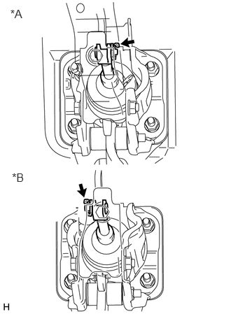
for LHD:
Set the master cylinder push rod clevis in place, insert the push rod pin from the left side of the vehicle and then install a new clip.
| *A | for LHD |
| *B | for RHD |
for RHD:
Set the master cylinder push rod clevis in place, insert the push rod pin from the right side of the vehicle and then install a new clip.
47101A
3.INSTALL BRAKE PEDAL RETURN SPRING
Apply a light coat of lithium soap base glycol grease to the inner surface of the hole on the brake pedal support sub-assembly.
Install the brake pedal return spring to the brake pedal support sub-assembly.
84341
4.CONNECT BRAKE PEDAL LOAD SENSING SWITCH
Connect the brake pedal load sensing switch connector.
84340
5.INSTALL STOP LIGHT SWITCH ASSEMBLY
Install the stop light switch assembly (See page Vehicle Exterior>LIGHTING (EXT)>STOP LIGHT SWITCH>INSTALLATION).
Connect the stop light switch connector.
73900
6.INSTALL LOWER NO. 1 INSTRUMENT PANEL AIRBAG ASSEMBLY
Install the lower No. 1 instrument panel airbag assembly (See page Vehicle Interior>SUPPLEMENTAL RESTRAINT SYSTEMS>KNEE AIRBAG ASSEMBLY>INSTALLATION).
7.CONNECT CABLE TO NEGATIVE BATTERY TERMINAL
8.BLEED BRAKE SYSTEM
9.FILL RESERVOIR WITH BRAKE FLUID
10.BLEED CLUTCH LINE
11.CHECK FLUID LEVEL IN RESERVOIR
12.CHECK FOR BRAKE FLUID LEAK FROM CLUTCH LINE
13.CHECK AND ADJUST BRAKE PEDAL
Check and adjust brake pedal (See page Brake>BRAKE SYSTEM (OTHER)>BRAKE PEDAL (for Vacuum Brake Booster)>ADJUSTMENT).
14. INITIALIZATION AFTER RECONNECTING BATTERY TERMINAL
Click hereGeneral>SETUP>WHEN DISCONNECTING OR RECONNECTING BATTERY TERMINAL>WORK PROCEDURE
- HINT:
-
When disconnecting and reconnecting the battery, there is an automatic learning function that completes learning when the respective system is used.
-
Click hereGeneral>SETUP>WHEN DISCONNECTING OR RECONNECTING BATTERY TERMINAL>AUTOMATIC LEARNING CHART