ACIS Control Circuit
Circuit diagnosis · Vehicles built Sep 2011 – Dec 2011
DESCRIPTION
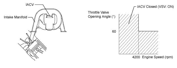
This circuit opens and closes the Intake Air Control Valve (IACV) in response to the engine load in order to increase the intake efficiency (ACIS: Acoustic Control Induction System).When the engine speed is 4200 rpm or more and the throttle valve opening angle is 60° or more, the IACV is open (VSV: OFF). At all other times, the IACV is closed (VSV: ON).

WIRING DIAGRAM
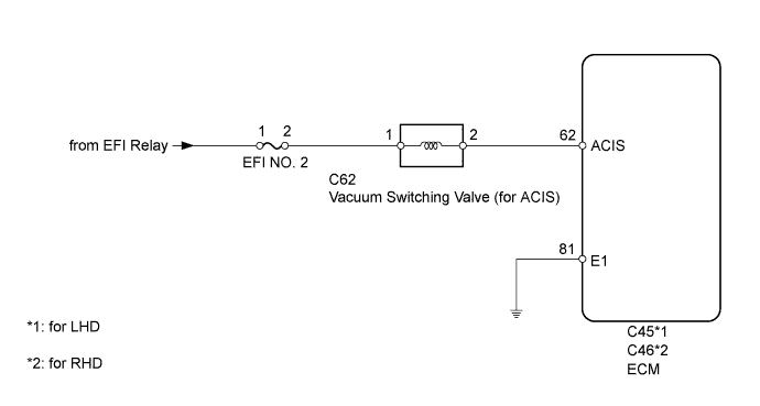
INSPECTION PROCEDURE
| 1. PERFORM ACTIVE TEST USING INTELLIGENT TESTER (OPERATE VSV (for ACIS)) |

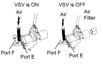 |
Disconnect the vacuum hose from port F on the vacuum switching valve (for ACIS).
Connect the intelligent tester to the DLC3.
Start the engine.
Enter the following menus: Powertrain / Engine and ECT / Active Test / Active the VSV for Intake Control.
Operate the VSV for ACIS.
Check the VSV air flow when switching the VSV.
- OK:
Test Condition
Specified Condition
VSV is ON
Air from port E flows out through port F
VSV is OFF
Air from port E flows out through air filter
|
|
||||

| OK | |
 |
| 2. INSPECT INTAKE MANIFOLD (INTAKE AIR CONTROL VALVE OPERATION) |
Inspect the intake air control valve operation (Click here).
|
|
||||

| OK | ||
 |
||
| ||
| 3. INSPECT VACUUM SWITCHING VALVE (for ACIS) |
Inspect the vacuum switching valve (Click here).
|
|
||||
| OK | |
|
| 4. INSPECT VACUUM SWITCHING VALVE (POWER SOURCE VOLTAGE) |
Disconnect the VSV connector.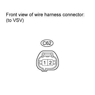
Turn the engine switch on (IG).
Measure the voltage according to the value(s) in the table below.
- Standard Voltage:
Tester Connection
Switch Condition
Specified Condition
C62-1 - Body ground
Engine switch on (IG)
11 to 14 V
|
|
||||
| OK | |
|
| 5. CHECK HARNESS AND CONNECTOR (VSV - ECM)) |
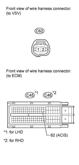 |
Disconnect the VSV connector.
Disconnect the ECM connector.
Measure the resistance according to the value(s) in the table below.
- Standard Resistance (for LHD):
Tester Connection
Condition
Specified Condition
C62-2 - C45-62 (ACIS)
Always
Below 1 Ω
C62-2 or C45-62 (ACIS) - Body ground
Always
10 kΩ or higher
- Standard Resistance (for RHD):
Tester Connection
Condition
Specified Condition
C62-2 - C46-62 (ACIS)
Always
Below 1 Ω
C62-2 or C46-62 (ACIS) - Body ground
Always
10 kΩ or higher
|
|
||||
| OK | |
|
| 6. REPLACE ECM |
Replace the ECM (Click here).
| NEXT | |
|
| 7. CHECK PROBLEM SYMPTOM DISAPPEARS |
Check if the problem symptom disappears.
Result Result
Proceed to
Problem symptom disappears
A
Problem symptom does not disappear
B
|
|
||||
| A | ||
|
||
| ||
| 8. CHECK HARNESS AND CONNECTOR (VSV - EFI NO. 2 FUSE) |
Disconnect the VSV connector.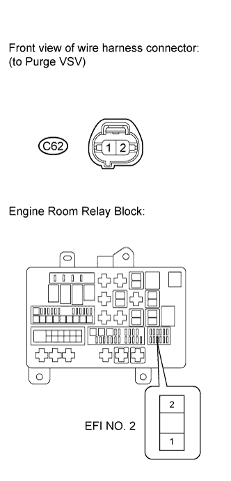
Remove the EFI No. 2 fuse from the engine room relay block.
Measure the resistance according to the value(s) in the table below.
- Standard Resistance:
Tester Connection
Condition
Specified Condition
C62-1 - EFI No. 2 fuse terminal 2
Always
Below 1 Ω
C62-1 or EFI No. 2 fuse terminal 2 - Body ground
Always
10 kΩ or higher
|
|
||||
| OK | ||
|
||
| ||