Home › Engine / Hybrid System › 1VD-FTV (ENGINE CONTROL) › ECD SYSTEM (w/ DPF) › 2014.08–2015.08
RM2660E _51 Engine / Hybrid System _052773 1VD-FTV ENGINE CONTROL _0254999 ECD SYSTEM(w/ DPF) J

1VD-FTV ENGINE CONTROL  ECD SYSTEM(w/ DPF)  Cranking Holding Function Circuit  


DESCRIPTION

The cranking holding control system provides current to the starter when the ECM detects the engine switch start signal (STSW). When the ECM performs a firing judgment, the system cuts current to the starter. When an ECM receives the STSW signal, it turns on the ST CUT relay, which prevents flickering of the combination meter, clock, audio system, etc. Also, the ECM sends a signal to the ECM STAR terminal of the ECM. Then the STAR output signal travels through the park/neutral position (PNP) switch to the ST relay, causing the starter to activate.

When the engine is cranking, the starter operation signal is sent to the ECM STA terminal of the ECM.
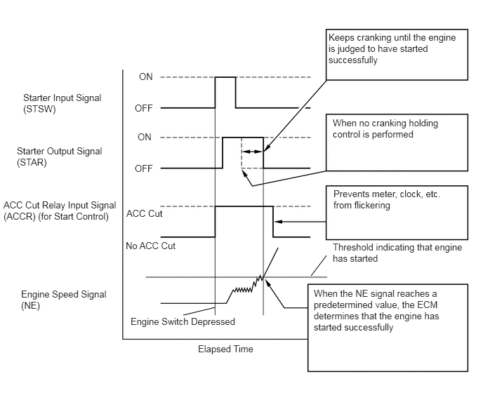
A103821E82
3.188,4.563 2.719,4.677 false 4.615,4.094 4.844,3.792 false 0.344,1.365 1.594,1.729 1.25,0.365 10 false Starter Input Signal (STSW) 0.25,2.156 1.635,2.51 1.385,0.354 10 false Starter Output Signal (STAR) 0.052,2.958 1.781,3.51 1.729,0.552 10 false ACC Cut Relay Input Signal (ACCR) (for Start Control) 0.313,4.281 1.656,4.646 1.344,0.365 10 false Engine Speed Signal (NE) 2.063,1.052 2.365,1.25 0.302,0.198 10 false ON 2,1.521 2.406,1.74 0.406,0.219 10 false OFF 2.042,1.948 2.344,2.146 0.302,0.198 10 false ON 2,2.417 2.406,2.635 0.406,0.219 10 false OFF 1.875,3.083 2.531,3.333 0.656,0.25 10 false ACC Cut 1.938,4.688 3.635,4.896 1.698,0.208 10 false Engine Switch Depressed 2.938,5.094 3.844,5.323 0.906,0.229 10 false Elapsed Time 4.875,0.469 6.844,1.021 1.969,0.552 10 false Keeps cranking until the engine is judged to have started successfully 4.938,1.74 6.646,2.125 1.708,0.385 10 false When no cranking holding control is performed 4.948,2.792 6.656,3.167 1.708,0.375 10 false Prevents meter, clock, etc. from flickering 4.938,3.583 6.927,4 1.99,0.417 10 false Threshold indicating that engine has started 4.656,4.271 6.594,4.99 1.938,0.719 10 false When the NE signal reaches a predetermined value, the ECM determines that the engine has started successfully 1.865,3.563 2.688,3.781 0.823,0.219 10 false No ACC Cut

CAUTION / NOTICE / HINT

NOTICE:
·

Inspect the fuses of circuits related to this system before performing the following inspection procedure.


PROCEDURE

1.CHECK CRANKING
a.

Check the cranking of the engine.

Result:
Test Result Proceed to
Cranking possible and holding control operates A
Does not crank B
Cranking possible but holding control does not operate C


A

PROCEED TO NEXT CIRCUIT INSPECTION SHOWN IN PROBLEM SYMPTOMS TABLE

B

2.READ VALUE USING GTS (STARTER SIGNAL)

C

11.CHECK HARNESS AND CONNECTOR (MAIN BODY ECU - ECM)
2.READ VALUE USING GTS (STARTER SIGNAL)
a.

Connect the GTS to the DLC3.


b.

Turn the engine switch on (IG).


c.

Turn the GTS on.


d.

Enter the following menus: Powertrain / Engine and ECT / Data List / Starter Signal.


e.

Read the values.


f.

Check the result when the engine switch is turned on (IG) and when the engine is started.

OK:
Engine Switch Condition Display (Starter Signal)
On (IG) Close
Engine started Open


OK

3.INSPECT STARTER RELAY (ST)

NG

7.INSPECT STARTER CUT RELAY (ST CUT)
3.INSPECT STARTER RELAY (ST)
a.


OK

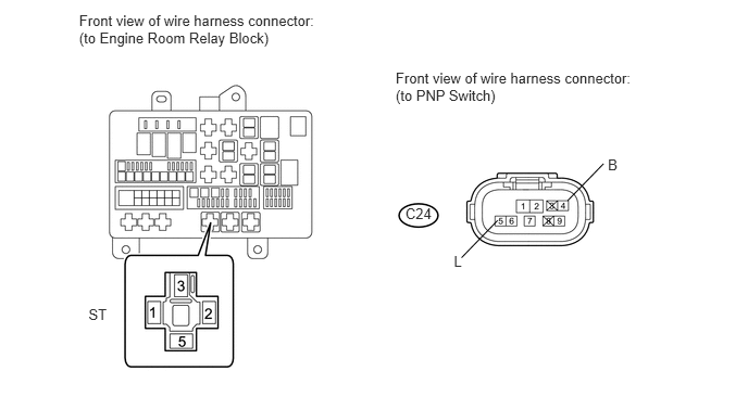
4.CHECK HARNESS AND CONNECTOR (PNP SWITCH - ST RELAY)

NG

REPLACE STARTER RELAY (ST)

4.CHECK HARNESS AND CONNECTOR (PNP SWITCH - ST RELAY)
U163711E01
4.422,2.474 4.767,2.117 false 3.791,0.668 6.162,1.018 2.371,0.350 10 Front view of wire harness connector: (to PNP Switch) 3.884,1.974 4.197,2.139 0.313,0.165 10 C24 0.848,2.94 1.087,3.094 0.239,0.154 10 ST 0.758,0.115 3.129,0.465 2.371,0.350 10 Front view of wire harness connector: (to Engine Room Relay Block) 5.438,1.927 5.783,1.571 false 5.824,1.504 5.980,1.655 0.156,0.151 10 B 4.348,2.424 4.504,2.575 0.156,0.151 10 L

a.

Disconnect the Park/Neutral Position (PNP) switch.


b.

Remove the ST relay from the engine room relay block.


c.

Measure the resistance according to the value(s) in the table below.

Standard Resistance:
Tester Connection Condition Specified Condition
ST relay (2) - C24-5 (L) Always Below 1 Ω
ST relay (2) or C24-5 (L) - Body ground Always 10 kΩ or higher


OK

5.CHECK HARNESS AND CONNECTOR (POWER SOURCE)

NG

REPAIR OR REPLACE HARNESS OR CONNECTOR

5.CHECK HARNESS AND CONNECTOR (POWER SOURCE)
A275266E01
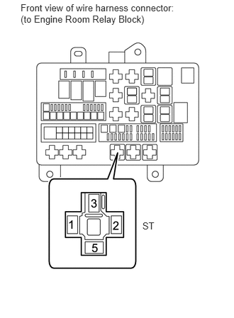
0.303,0.027 2.642,0.368 2.339,0.341 10 Front view of wire harness connector: (to Engine Room Relay Block) 2.092,3.235 2.331,3.401 0.239,0.165 10 ST

a.

Remove the ST relay from the engine room relay block.


b.

Measure the voltage according to the value(s) in the table below.

Standard Voltage:
Tester Connection Condition Specified Condition
ST relay (1) - ST relay (5) Always 11 to 14 V


OK

6.INSPECT STARTER

NG

REPAIR OR REPLACE HARNESS OR CONNECTOR (STARTER RELAY (ST) - BATTERY, BODY GROUND)

6.INSPECT STARTER
a.

Inspect the starter (See page Engine / Hybrid System>1VD-FTV (STARTING)>STARTER>INSPECTION).

Result:
Test Result Proceed to
OK A
NG B


A

REPAIR OR REPLACE HARNESS OR CONNECTOR (STARTER - STARTER RELAY (ST), BATTERY)

B

7.INSPECT STARTER CUT RELAY (ST CUT)
a.

Inspect the starter cut relay (ST CUT) (See page Engine / Hybrid System>1VD-FTV (STARTING)>RELAY>ON-VEHICLE INSPECTION).


OK

8.CHECK HARNESS AND CONNECTOR (ST CUT RELAY - PNP SWITCH, ECM)

NG

REPLACE STARTER CUT RELAY (ST CUT)

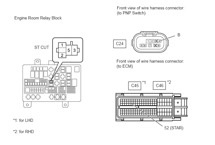
8.CHECK HARNESS AND CONNECTOR (ST CUT RELAY - PNP SWITCH, ECM)
A384944E01
3.781,1.323 4.198,1.594 0.417,0.271 4.281,2.719 4.698,2.99 0.417,0.271 5.104,2.708 5.521,2.979 0.417,0.271 5.344,1.354 5.833,1.188 true 4.396,3.458 5.417,4.198 true 0.479,0.51 2.292,0.708 1.813,0.198 10 false Engine Room Relay Block 3.896,0.177 6.219,0.552 2.323,0.375 10 false Front view of wire harness connector: (to PNP Switch) 3.865,1.365 4.219,1.563 0.354,0.198 10 false C24 5.917,1.073 6.271,1.271 0.354,0.198 10 false B 3.885,1.948 6.208,2.323 2.323,0.375 10 false Front view of wire harness connector: (to ECM) 4.375,2.76 4.729,2.958 0.354,0.198 10 false C45 5.198,2.76 5.552,2.958 0.354,0.198 10 false C46 4.74,2.656 5.094,2.854 0.354,0.198 10 false *1 5.573,2.646 5.927,2.844 0.354,0.198 10 false *2 5.479,4.167 6.26,4.375 0.781,0.208 10 false 52 (STAR) 0.438,3.917 1.219,4.125 0.781,0.208 10 false *1: for LHD 0.438,4.292 1.219,4.5 0.781,0.208 10 false *2: for RHD 1.146,1.49 1.708,1.698 0.563,0.208 10 false ST CUT

a.

Remove the starter cut relay (ST CUT) from the engine room relay block.


b.

Disconnect the PNP switch connector.


c.

Disconnect the ECM connector.


d.

Measure the resistance according to the value(s) in the table below.

Standard Resistance:
for LHD
Tester Connection Condition Specified Condition
ST CUT relay (5) - C45-52 (STAR) Always Below 1 Ω
ST CUT relay (3) - C24-4 (B) Always Below 1 Ω
ST CUT relay (5) or C45-52 (STAR) - Body ground Always 10 kΩ or higher
ST CUT relay (3) or C24-4 (B) - Body ground Always 10 kΩ or higher

for RHD
Tester Connection Condition Specified Condition
ST CUT relay (5) - C46-52 (STAR) Always Below 1 Ω
ST CUT relay (3) - C24-4 (B) Always Below 1 Ω
ST CUT relay (5) or C46-52 (STAR) - Body ground Always 10 kΩ or higher
ST CUT relay (3) or C24-4 (B) - Body ground Always 10 kΩ or higher


OK

9.INSPECT PARK/NEUTRAL POSITION SWITCH

NG

REPAIR OR REPLACE HARNESS OR CONNECTOR

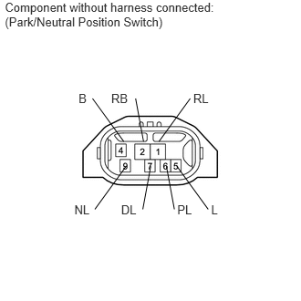
9.INSPECT PARK/NEUTRAL POSITION SWITCH
a.
C160109E06
0.056,0.001 2.638,0.368 2.582,0.367 10 Component without harness connected: (Park/Neutral Position Switch) 1.27,1.041 1.484,1.222 0.213,0.181 10 RB 0.897,1.041 1.046,1.222 0.149,0.181 10 B 2.024,2.312 2.234,2.493 0.210,0.181 10 PL 2.411,2.312 2.621,2.493 0.210,0.181 10 L 2.377,2.39 2.02,1.898 false 1.383,2.312 1.593,2.493 0.210,0.181 10 DL 1.63,2.39 1.721,1.898 false 0.849,2.312 1.059,2.493 0.210,0.181 10 NL 2.207,1.041 2.420,1.222 0.213,0.181 10 RL 1.991,2.39 1.9,1.898 false 1.639,1.616 1.548,1.124 false 1.083,2.39 1.44,1.898 false 1.815,1.616 2.172,1.124 false 1.413,1.616 1.056,1.124 false

Inspect the Park/Neutral Position (PNP) switch.

i.

Disconnect the PNP switch connector.


ii.

Measure the resistance according to the value(s) in the table below.

Standard Resistance:
Tester Connection Condition Specified Condition
4 (B) - 5 (L) Shift lever in P Below 1 Ω
Shift lever in N Below 1 Ω


OK

10.CHECK HARNESS AND CONNECTOR (PNP SWITCH - ECM)

NG

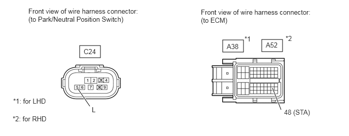
10.CHECK HARNESS AND CONNECTOR (PNP SWITCH - ECM)
A384946E01
1.635,0.938 2.063,1.188 0.427,0.25 4.573,0.823 5,1.073 0.427,0.25 5.375,0.813 5.802,1.063 0.427,0.25 5.594,1.813 5.771,2.26 true 1.594,1.823 1.844,2.188 true 0.583,0.146 2.917,0.51 2.333,0.365 10 false Front view of wire harness connector: (to Park/Neutral Position Switch) 4.125,0.167 6.458,0.531 2.333,0.365 10 false Front view of wire harness connector: (to ECM) 1.719,0.979 2.052,1.177 0.333,0.198 10 false C24 4.656,0.875 4.99,1.073 0.333,0.198 10 false A38 5.458,0.844 5.792,1.042 0.333,0.198 10 false A52 5.021,0.719 5.292,0.917 0.271,0.198 10 false *1 5.865,0.708 6.135,0.906 0.271,0.198 10 false *2 5.833,2.229 6.542,2.427 0.708,0.198 10 false 48 (STA) 0.271,2 1.042,2.229 0.771,0.229 10 false *1: for LHD 0.26,2.365 1.031,2.594 0.771,0.229 10 false *2: for RHD 1.885,2.177 2.594,2.375 0.708,0.198 10 false L

a.

Disconnect the PNP switch connector.


b.

Disconnect the ECM connector.


c.

Measure the resistance according to the value(s) in the table below.

Standard Resistance:
for LHD
Tester Connection Condition Specified Condition
C24-5 (L) - A38-46 (STA) Always Below 1 Ω
C24-5 (L) or A38-46 (STA) - Body ground Always 10 kΩ or higher

for RHD
Tester Connection Condition Specified Condition
C24-5 (L) - A52-46 (STA) Always Below 1 Ω
C24-5 (L) or A52-46 (STA) - Body ground Always 10 kΩ or higher


Result
Result Proceed to
NG A
OK B


A

REPAIR OR REPLACE HARNESS OR CONNECTOR

B

13.REPLACE ECM
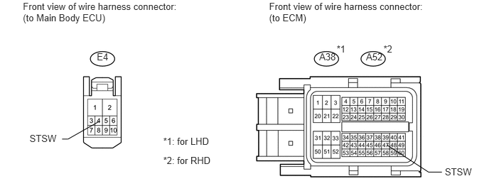
11.CHECK HARNESS AND CONNECTOR (MAIN BODY ECU - ECM)
U163025E01
1.419,0.747 1.794,0.980 0.375,0.233 10 E4 4.679,0.753 5.054,0.986 0.375,0.233 10 A38 4.934,0.637 5.108,0.817 0.174,0.180 10 *1 5.365,0.753 5.740,0.986 0.375,0.233 10 A52 5.62,0.637 5.794,0.817 0.174,0.180 10 *2 0.336,0.01 2.745,0.377 2.409,0.367 10 Front view of wire harness connector: (to Main Body ECU) 3.944,0.01 6.352,0.377 2.408,0.367 10 Front view of wire harness connector: (to ECM) 6.52,2.435 6.986,2.637 0.466,0.202 10 STSW 0.433,1.951 0.895,2.153 0.462,0.202 10 STSW 0.91,2.04 0.997,2.04 0.997,2.04 1.452,1.781 false 6.476,2.524 6.28,2.524 6.28,2.524 5.671,2.127 false 2.392,1.994 3.184,2.196 0.793,0.202 10 *1: for LHD 2.392,2.271 3.205,2.473 0.813,0.202 10 *2: for RHD

a.

Disconnect the main body ECU connector.


b.

Disconnect the ECM connector.


c.

Measure the resistance according to the value(s) in the table below.

Standard Resistance:
for LHD
Tester Connection Condition Specified Condition
E4-4 (STSW) - A38-47 (STSW) Always Below 1 Ω
E4-4 (STSW) or A38-47 (STSW) - Body ground Always 10 kΩ or higher

for RHD
Tester Connection Condition Specified Condition
E4-4 (STSW) - A52-47 (STSW) Always Below 1 Ω
E4-4 (STSW) or A52-47 (STSW) - Body ground Always 10 kΩ or higher


OK

12.CHECK HARNESS AND CONNECTOR (ST CUT RELAY - PNP SWITCH, ECM)

NG

REPAIR OR REPLACE HARNESS OR CONNECTOR

12.CHECK HARNESS AND CONNECTOR (ST CUT RELAY - PNP SWITCH, ECM)
A384944E01
3.781,1.323 4.198,1.594 0.417,0.271 4.281,2.719 4.698,2.99 0.417,0.271 5.104,2.708 5.521,2.979 0.417,0.271 5.344,1.354 5.833,1.188 true 4.396,3.458 5.417,4.198 true 0.479,0.51 2.292,0.708 1.813,0.198 10 false Engine Room Relay Block 3.896,0.177 6.219,0.552 2.323,0.375 10 false Front view of wire harness connector: (to PNP Switch) 3.865,1.365 4.219,1.563 0.354,0.198 10 false C24 5.917,1.073 6.271,1.271 0.354,0.198 10 false B 3.885,1.948 6.208,2.323 2.323,0.375 10 false Front view of wire harness connector: (to ECM) 4.375,2.76 4.729,2.958 0.354,0.198 10 false C45 5.198,2.76 5.552,2.958 0.354,0.198 10 false C46 4.74,2.656 5.094,2.854 0.354,0.198 10 false *1 5.573,2.646 5.927,2.844 0.354,0.198 10 false *2 5.479,4.167 6.26,4.375 0.781,0.208 10 false 52 (STAR) 0.438,3.917 1.219,4.125 0.781,0.208 10 false *1: for LHD 0.438,4.292 1.219,4.5 0.781,0.208 10 false *2: for RHD 1.146,1.49 1.708,1.698 0.563,0.208 10 false ST CUT

a.

Remove the starter cut relay (ST CUT) from the engine room relay block.


b.

Disconnect the PNP switch connector.


c.

Disconnect the ECM connector.


d.

Measure the resistance according to the value(s) in the table below.

Standard Resistance:
for LHD
Tester Connection Condition Specified Condition
ST CUT relay (5) - C45-52 (STAR) Always Below 1 Ω
ST CUT relay (3) - C24-4 (B) Always Below 1 Ω
ST CUT relay (5) or C45-52 (STAR) - Body ground Always 10 kΩ or higher
ST CUT relay (3) or C24-4 (B) - Body ground Always 10 kΩ or higher

for RHD
Tester Connection Condition Specified Condition
ST CUT relay (5) - C46-52 (STAR) Always Below 1 Ω
ST CUT relay (3) - C24-4 (B) Always Below 1 Ω
ST CUT relay (5) or C46-52 (STAR) - Body ground Always 10 kΩ or higher
ST CUT relay (3) or C24-4 (B) - Body ground Always 10 kΩ or higher


OK

NG
REPAIR OR REPLACE HARNESS OR CONNECTOR

13.REPLACE ECM

NEXT

14.CONFIRM WHETHER MALFUNCTION HAS BEEN SUCCESSFULLY REPAIRED
a.

Check the starter operation.

OK:

Malfunction has been repaired successfully.


OK

END

NG