1UR-FE ENGINE MECHANICAL CYLINDER HEAD GASKET REMOVAL
PROCEDURE

 17140
1.REMOVE EXHAUST MANIFOLD ASSEMBLY
13053
2.REMOVE CAMSHAFT SUB-ASSEMBLY
13801
3.REMOVE NO. 1 VALVE ROCKER ARM SUB-ASSEMBLY
Remove the 32 No. 1 valve rocker arms from the cylinder head.
- HINT:
-
Arrange the removed parts in the correct order.
13750
4.REMOVE VALVE LASH ADJUSTER ASSEMBLY
Remove the 32 valve lash adjusters from the cylinder head.
- HINT:
-
Arrange the removed parts in the correct order.
13716
5.REMOVE VALVE STEM CAP
Remove the 32 valve stem caps from the cylinder head.
- HINT:
-
Arrange the removed parts in the correct order.
11102
6.REMOVE CYLINDER HEAD SUB-ASSEMBLY LH
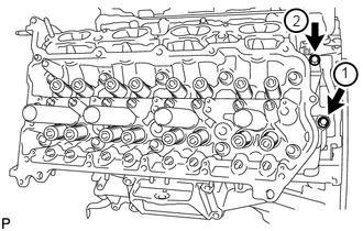
Uniformly loosen and remove the 2 bolts in the sequence shown in the illustration.
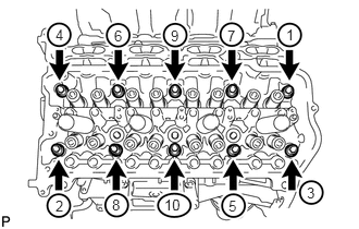
Using a 10 mm bi-hexagon wrench, uniformly loosen the 10 cylinder head bolts in the sequence shown in the illustration. Remove the 10 cylinder head bolts and plate washers.
- NOTICE:
- ·
Be careful not to drop washers into the cylinder head.
·Head warpage or cracking could result from removing bolts in an incorrect order.
- HINT:
-
Be sure to arrange the removed parts for each installation position separately.
Remove the cylinder head LH.
11116
7.REMOVE NO. 2 CYLINDER HEAD GASKET
11101
8.REMOVE CYLINDER HEAD SUB-ASSEMBLY
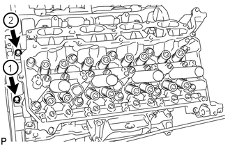
Uniformly loosen and remove the 2 bolts in the sequence shown in the illustration.
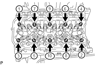
Using a 10 mm bi-hexagon wrench, uniformly loosen the 10 cylinder head bolts in the sequence shown in the illustration. Remove the 10 cylinder head bolts and plate washers.
- NOTICE:
- ·
Be careful not to drop washers into the cylinder head.
·Head warpage or cracking could result from removing bolts in an incorrect order.
- HINT:
-
Be sure to arrange the removed parts for each installation position separately.
Remove the cylinder head.
11115
9.REMOVE CYLINDER HEAD GASKET
11101A
10.INSPECT CYLINDER HEAD SET BOLT
11102
11.INSPECT CYLINDER HEAD SUB-ASSEMBLY