1UR-FE INTAKE / EXHAUST EXHAUST MANIFOLD REMOVAL
PROCEDURE

 11209
1.REMOVE V-BANK COVER SUB-ASSEMBLY
2.REMOVE AIR CLEANER AND HOSE
53806
3.REMOVE FRONT FENDER SPLASH SHIELD SUB-ASSEMBLY LH
53805
4.REMOVE FRONT FENDER SPLASH SHIELD SUB-ASSEMBLY RH
51405A
5.REMOVE NO. 1 ENGINE UNDER COVER SUB-ASSEMBLY
51442
6.REMOVE NO. 2 ENGINE UNDER COVER
53783
7.REMOVE FRONT FENDER APRON TRIM PACKING B
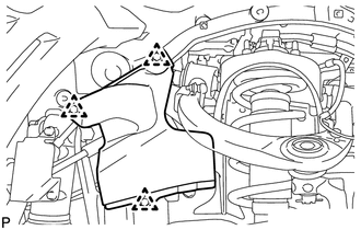
w/ KDSS:
Remove the 3 clips and front fender apron trim packing B.
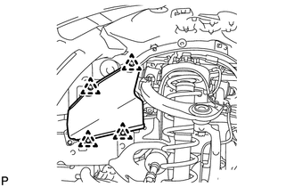
w/o KDSS:
Remove the 4 clips and front fender apron trim packing B.
53785B
8.REMOVE FRONT FENDER APRON TRIM PACKING D
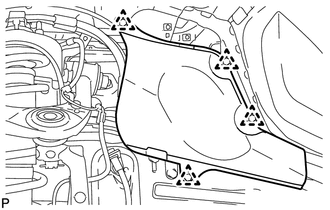
Remove the 4 clips and front fender apron trim packing D.
53782
9.REMOVE FRONT FENDER APRON TRIM PACKING A
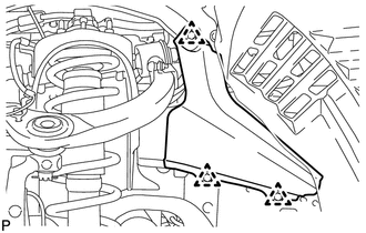
Remove the 3 clips and front fender apron trim packing A.
53784
10.REMOVE FRONT FENDER APRON TRIM PACKING C
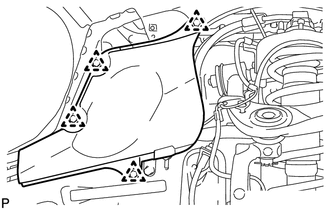
Remove the 4 clips and front fender apron trim packing C.
17410
11.REMOVE FRONT EXHAUST PIPE ASSEMBLY
37140
12.REMOVE FRONT PROPELLER SHAFT ASSEMBLY
37117
13.REMOVE PROPELLER SHAFT HEAT INSULATOR
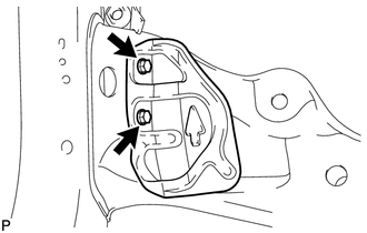
Remove the 2 bolts and heat insulator.
17119
14.REMOVE NO. 2 MANIFOLD STAY
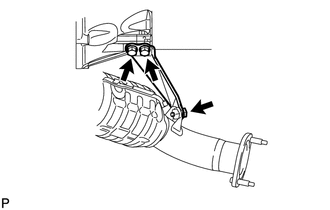
Remove the 3 bolts and No. 2 manifold stay.
17168
15.REMOVE NO. 2 EXHAUST MANIFOLD HEAT INSULATOR
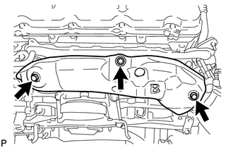
Remove the 3 bolts and No. 2 exhaust manifold heat insulator.
17150
16.REMOVE EXHAUST MANIFOLD ASSEMBLY LH
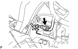
Disconnect the air fuel ratio sensor connector and detach the wire harness clamp.
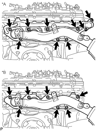
w/ Secondary Air Injection System:
Remove the 9 nuts, exhaust manifold and 2 gaskets.
| *A | w/ Secondary Air Injection System |
| *B | w/o Secondary Air Injection System |
w/o Secondary Air Injection System:
Remove the 7 nuts, exhaust manifold and gasket.
17118
17.REMOVE MANIFOLD STAY
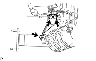
Remove the 3 bolts and manifold stay.
11452
18.REMOVE ENGINE OIL LEVEL DIPSTICK GUIDE
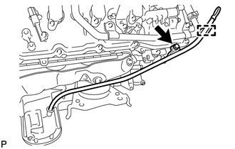
Remove the engine oil level dipstick.
Detach the engine wire clamp.
Remove the bolt and engine oil level dipstick guide.
Remove the O-ring from the engine oil level dipstick guide.
17167
19.REMOVE NO. 1 EXHAUST MANIFOLD HEAT INSULATOR
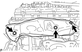
Remove the 3 bolts and heat insulator.
17140
20.REMOVE EXHAUST MANIFOLD ASSEMBLY RH
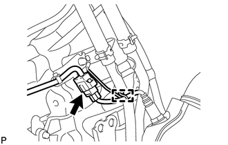
Disconnect the air fuel ratio sensor connector and detach the wire harness clamp.
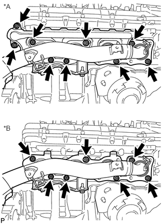
w/ Secondary Air Injection System:
Remove the 9 nuts, exhaust manifold and 2 gaskets.
| *A | w/ Secondary Air Injection System |
| *B | w/o Secondary Air Injection System |
w/o Secondary Air Injection System:
Remove the 7 nuts, exhaust manifold and 2 gaskets.
89467B
21.REMOVE AIR FUEL RATIO SENSOR (for Bank 1 Sensor 1)
89467B
22.REMOVE AIR FUEL RATIO SENSOR (for Bank 2 Sensor 1)