1VD-FTV FUEL FUEL SENDER GAUGE ASSEMBLY(for Fuel Sub Tank) INSTALLATION
PROCEDURE

 83320B
1.INSTALL FUEL SENDER GAUGE ASSEMBLY
Install a new gasket to the fuel sender gauge assembly.
Install the sender gauge with the 5 screws.
- Torque:
- 1.5 N*m (15 kgf*cm, 13 in.*lbf)
- NOTICE:
-
Be careful not to bend the arm of the fuel sender gauge assembly.
Connect the fuel sender gauge connector.
58325E
2.INSTALL REAR FLOOR SERVICE HOLE COVER
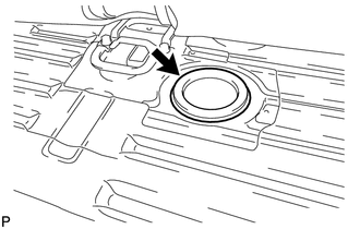
Install the rear floor service hole cover with new butyl tape.
87212L
3.INSTALL REAR NO. 7 AIR DUCT (w/ Rear Air Conditioning System)
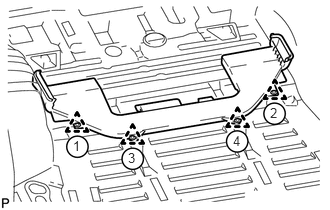
Attach the 4 clips to install the rear No. 7 air duct.
- HINT:
-
Attach the clips in the order shown in the illustration.
58570C
4.INSTALL REAR FLOOR MAT ASSEMBLY
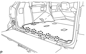
Attach the 5 clips to install the rear floor mat assembly.
87174
5.INSTALL REAR AIR DUCT GUIDE (w/ Rear Air Conditioning System)
87217B
6.INSTALL AIR DUCT PLUG (w/ Rear Air Conditioning System)
62520P
7.INSTALL FRONT QUARTER TRIM PANEL ASSEMBLY LH
w/ Sliding Roof:
(See page Vehicle Interior>INTERIOR PANELS / TRIM>ROOF HEADLINING (w/ Sliding Roof)>INSTALLATION)
w/o Sliding Roof:
(See page Vehicle Interior>INTERIOR PANELS / TRIM>ROOF HEADLINING (w/o Sliding Roof)>INSTALLATION)
62510P
8.INSTALL FRONT QUARTER TRIM PANEL ASSEMBLY RH
w/ Sliding Roof:
(See page Vehicle Interior>INTERIOR PANELS / TRIM>ROOF HEADLINING (w/ Sliding Roof)>INSTALLATION)
w/o Sliding Roof:
(See page Vehicle Interior>INTERIOR PANELS / TRIM>ROOF HEADLINING (w/o Sliding Roof)>INSTALLATION)
71845B
9.INSTALL REAR SEAT COVER CAP (w/ Rear No. 2 Seat, except Face to Face Seat Type)
58574A
10.INSTALL REAR FLOOR MAT REAR SUPPORT PLATE
67918E
11.INSTALL REAR DOOR SCUFF PLATE LH
67917C
12.INSTALL REAR DOOR SCUFF PLATE RH
51775
13.INSTALL REAR STEP COVER
14.INSTALL REAR NO. 2 SEAT ASSEMBLY
for Face to Face Seat Type:
(See page Vehicle Interior>SEAT>REAR NO. 2 SEAT ASSEMBLY(for Face to Face Seat Type)>INSTALLATION)
except Face to Face Seat Type:
(See page Vehicle Interior>SEAT>REAR NO. 2 SEAT ASSEMBLY(except Face to Face Seat Type)>INSTALLATION)
71300S
15.INSTALL REAR NO. 1 SEAT ASSEMBLY RH (for 60/40 Split Seat Type 40 Side)
71400S
16.INSTALL REAR NO. 1 SEAT ASSEMBLY LH (for 60/40 Split Seat Type 60 Side)
17.INSTALL CABLE TO NEGATIVE BATTERY TERMINAL
- NOTICE:
-
When disconnecting the cable, some systems need to be initialized after the cable is reconnected (See page General>INTRODUCTION>REPAIR INSTRUCTION>INITIALIZATION).
Connect the cables to the negative (-) main battery and sub-battery terminals.
18.CHECK SRS WARNING LIGHT