AUDIO / VIDEO STEREO COMPONENT AMPLIFIER INSTALLATION
PROCEDURE

 86286
1.INSTALL NO. 2 AMPLIFIER BRACKET
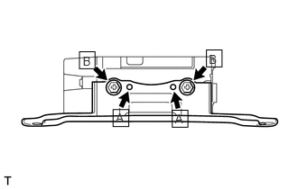
Set the aligning protrusions of the bracket labeled A, into the holes of the amplifier.
Install the bracket with the 2 screws labeled B.
- Torque:
- 3.0 N*m (30 kgf*cm, 26 in.*lbf)
86285
2.INSTALL NO. 1 AMPLIFIER BRACKET
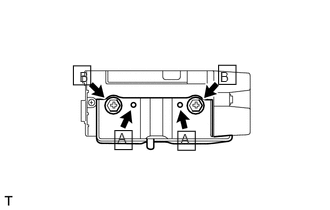
Set the aligning protrusions of the bracket labeled A, into the holes of the amplifier.
Install the bracket with the 2 screws labeled B.
- Torque:
- 3.0 N*m (30 kgf*cm, 26 in.*lbf)
86287B
3.INSTALL AMPLIFIER COVER
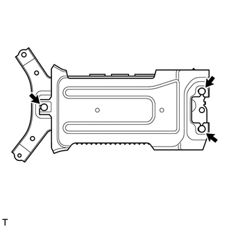
Attach the 3 clips to install the cover.
86280
4.INSTALL STEREO COMPONENT AMPLIFIER ASSEMBLY WITH BRACKET
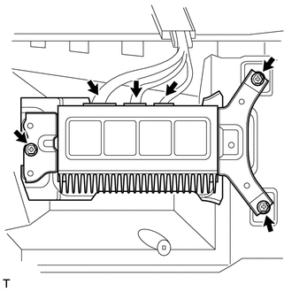
Install the amplifier with the 3 bolts.
- Torque:
- 7.5 N*m (76 kgf*cm, 66 in.*lbf)
Connect the 3 connectors.
58510D
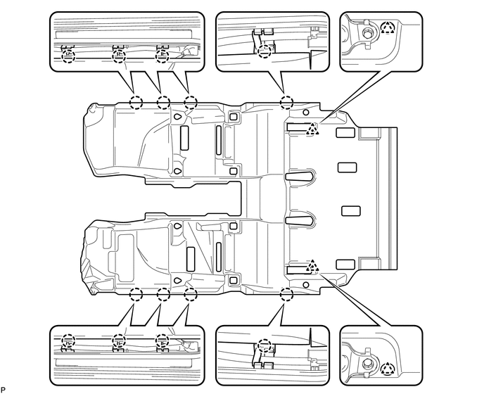
5.INSTALL FRONT FLOOR CARPET ASSEMBLY
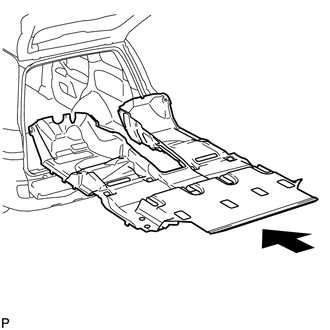
Open the tail gate and back door, insert the carpet into the cabin from the rear, and install it to the floor.
Attach the 2 clips and 8 claws.
58901A
6.INSTALL REAR CONSOLE BOX SUB-ASSEMBLY (w/o Cool Box)
Install the rear console box (See page Vehicle Interior>INTERIOR PANELS / TRIM>FRONT CONSOLE BOX(w/o Cool Box)>INSTALLATION).
88520
7.INSTALL COOLING BOX ASSEMBLY (w/ Cool Box)
Install the cooling box assembly (See page Vehicle Interior>INTERIOR PANELS / TRIM>FRONT CONSOLE BOX(w/ Cool Box)>INSTALLATION).
71696
8.INSTALL REAR NO. 2 SEAT PROTECTOR
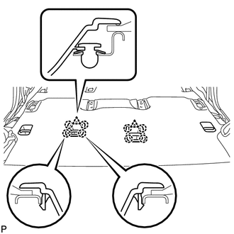
Attach the clip and 4 claws to install the protector.
- HINT:
-
Use the same procedures to install the protector on the other side.
71695C
9.INSTALL REAR NO. 1 SEAT PROTECTOR
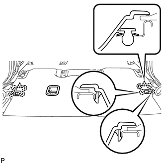
Attach the clip and 4 claws to install the protector.
- HINT:
-
Use the same procedures to install the protector on the other side.
87174
10.INSTALL REAR AIR DUCT GUIDE
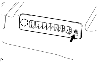
Attach the claw to install the guide.
Install the screw.
- HINT:
-
Use the same procedures for both sides.
87217B
11.INSTALL AIR DUCT PLUG
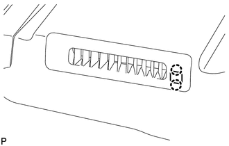
Attach the 2 claws to install the plug.
- HINT:
-
Use the same procedures for both sides.
87174F
12.INSTALL AIR HEATER GUIDE
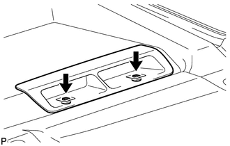
Install the guide with the 2 screws.
- HINT:
-
Use the same procedures for both sides.
87217J
13.INSTALL NO. 2 AIR DUCT PLUG
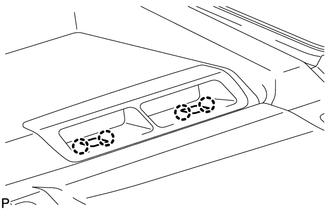
Attach the 4 claws to install the 2 plugs.
- HINT:
-
Use the same procedures for both sides.
67918E
14.INSTALL REAR DOOR SCUFF PLATE LH
67917C
15.INSTALL REAR DOOR SCUFF PLATE RH
51775
16.INSTALL REAR STEP COVER
62111C
17.INSTALL COWL SIDE TRIM BOARD RH
55607
18.INSTALL NO. 2 INSTRUMENT PANEL UNDER COVER SUB-ASSEMBLY (w/ Floor Under Cover)
62112
19.INSTALL COWL SIDE TRIM BOARD LH
55606
20.INSTALL NO. 1 INSTRUMENT PANEL UNDER COVER SUB-ASSEMBLY (w/ Floor Under Cover)
67914B
21.INSTALL FRONT DOOR SCUFF PLATE LH
67913B
22.INSTALL FRONT DOOR SCUFF PLATE RH
55317A
23.INSTALL INSTRUMENT SIDE PANEL RH (w/ Airbag Cut Off Switch)
55317A
24.INSTALL INSTRUMENT SIDE PANEL RH (w/o Airbag Cut Off Switch)
55318C
25.INSTALL INSTRUMENT SIDE PANEL LH
26.INSTALL REAR NO. 1 SEAT ASSEMBLY RH
71691J
27.INSTALL REAR NO. 3 SEAT CUSHION HINGE COVER
71691E
28.INSTALL REAR NO. 1 SEAT CUSHION HINGE COVER
71691J
29.INSTALL REAR NO. 4 SEAT CUSHION HINGE COVER
71691E
30.INSTALL REAR NO. 2 SEAT CUSHION HINGE COVER
31.INSTALL REAR NO. 1 SEAT ASSEMBLY LH
71691K
32.INSTALL REAR NO. 4 SEAT CUSHION HINGE COVER
71691H
33.INSTALL REAR NO. 2 SEAT CUSHION HINGE COVER
71691K
34.INSTALL REAR NO. 5 SEAT CUSHION HINGE COVER
71691H
35.INSTALL REAR NO. 3 SEAT CUSHION HINGE COVER
36.INSTALL FRONT SEAT ASSEMBLY RH
for Manual Seat:
Install the front seat assembly RH (See page Vehicle Interior>SEAT>FRONT SEAT ASSEMBLY (for Manual Seat)>INSTALLATION).
for Power Seat:
Install the front seat assembly RH (See page Vehicle Interior>SEAT>FRONT SEAT ASSEMBLY (for Power Seat)>INSTALLATION).
- HINT:
-
Use the same procedures described for the LH side.
37.INSTALL FRONT SEAT ASSEMBLY LH
for Manual Seat:
Install the front seat assembly LH (See page Vehicle Interior>SEAT>FRONT SEAT ASSEMBLY (for Manual Seat)>INSTALLATION).
for Power Seat:
Install the front seat assembly LH (See page Vehicle Interior>SEAT>FRONT SEAT ASSEMBLY (for Power Seat)>INSTALLATION).
38.CONNECT CABLE TO NEGATIVE BATTERY TERMINAL
- NOTICE:
-
When disconnecting the cable, some systems need to be initialized after the cable is reconnected (See page General>INTRODUCTION>REPAIR INSTRUCTION>INITIALIZATION).
39.CHECK SRS WARNING LIGHT
Check the SRS warning light (See page Vehicle Interior>SUPPLEMENTAL RESTRAINT SYSTEMS>AIRBAG SYSTEM>DIAGNOSIS SYSTEM).