Home › Engine / Hybrid System › CRUISE CONTROL › DYNAMIC RADAR CRUISE CONTROL SYSTEM › 2014.08–2015.08
RM2660E _51 Engine / Hybrid System _052804 CRUISE CONTROL _0255251 DYNAMIC RADAR CRUISE CONTROL SYSTEM J

CRUISE CONTROL  DYNAMIC RADAR CRUISE CONTROL SYSTEM  Distance Control Switch Circuit  


DESCRIPTION

The distance control switch sets the vehicle-to-vehicle distance control mode. The distance control switch is installed in the steering pad switch. The vehicle-to-vehicle distance set value can be changed by operating the steering pad switch (distance control switch) while the dynamic radar cruise control system is in operation. The steering pad switch uses the CAN communication line to communicate with each ECU.

WIRING DIAGRAM
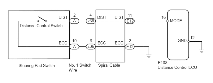
E158933E06
5.427,0.5 5.635,0.667 0.208,0.167 10 false 16 6.396,1.188 6.604,1.354 0.208,0.167 10 false 12 5.313,2.031 5.677,2.198 0.365,0.167 10 false E108 5.719,0.615 6.188,0.771 0.469,0.156 10 false MODE 5.979,1.281 6.333,1.438 0.354,0.156 10 false GND 3.302,2.115 4.146,2.406 0.844,0.292 10 false Spiral Cable 2.313,2.115 3.156,2.469 0.844,0.354 10 false No. 1 Switch Wire 4.26,0.625 4.531,0.792 0.271,0.167 10 false E12 4.302,0.438 4.49,0.615 0.188,0.177 10 false 11 3.01,0.417 3.177,0.594 0.167,0.177 10 false 4 2.469,0.427 2.573,0.615 0.104,0.188 10 false 2 3.854,0.5 4.198,0.688 0.344,0.188 10 false DIST 2.948,0.615 3.188,0.781 0.24,0.167 10 false z36 2.948,1.479 3.188,1.646 0.24,0.167 10 false z36 2.458,0.615 2.583,0.781 0.125,0.167 10 false A 2.458,1.49 2.594,1.656 0.135,0.167 10 false A 4.25,1.49 4.521,1.656 0.271,0.167 10 false E12 2.427,1.292 2.625,1.469 0.198,0.177 10 false 10 4.333,1.292 4.49,1.479 0.156,0.188 10 false 2 3.021,1.292 3.177,1.479 0.156,0.188 10 false 6 3.865,1.365 4.208,1.552 0.344,0.188 10 false ECC 1.969,0.5 2.313,0.688 0.344,0.188 10 false DIST 1.979,1.365 2.323,1.552 0.344,0.188 10 false ECC 3.271,0.5 3.615,0.688 0.344,0.188 10 false DIST 3.281,1.365 3.625,1.552 0.344,0.188 10 false ECC 0.625,2.125 1.917,2.302 1.292,0.177 10 false Steering Pad Switch 5.302,2.188 6.74,2.354 1.438,0.167 10 false Distance Control ECU 0.667,0.781 2.198,0.958 1.531,0.177 10 false Distance Control Switch

CAUTION / NOTICE / HINT

CAUTION:

The vehicle is equipped with an SRS (Supplemental Restraint System) which includes components such as airbags. Before servicing (including removal or installation of parts), be sure to read the Precaution for the SRS (See page Engine / Hybrid System>CRUISE CONTROL>DISTANCE CONTROL ECU>INITIALIZATION).


NOTICE:

When the distance control ECU is replaced with a new one, initialization must be performed (See page Vehicle Interior>SUPPLEMENTAL RESTRAINT SYSTEMS>AIRBAG SYSTEM>PRECAUTION).


PROCEDURE

1.READ VALUE USING INTELLIGENT TESTER (VEHICLE DISTANCE)
a.

Using the intelligent tester, read the Data List (See page Engine / Hybrid System>CRUISE CONTROL>DYNAMIC RADAR CRUISE CONTROL SYSTEM>DATA LIST / ACTIVE TEST).

Radar Cruise
Tester Display Measurement Item/Range Normal Condition Diagnostic Note
Car Dist Time Setting Vehicle distance time setting condition /
SHORT, LONG, MID or NO
Vehicle distance selected by steering pad switch (distance control switch) -

OK:

Normal conditions listed above are displayed.


OK

PROCEED TO NEXT CIRCUIT INSPECTION SHOWN IN PROBLEM SYMPTOMS TABLE

NG

2.CHECK NO. 1 SWITCH WIRE
a.
U166022E02
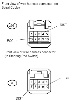
1.521,3.604 1.01,4.146 false 1.333,1.667 0.698,1.74 false 2.083,3.667 2.635,3.385 false 1.927,1.396 2.521,1.115 false 0.396,1.021 0.667,1.188 0.271,0.167 10 false z36 0.479,3.51 0.604,3.677 0.125,0.167 10 false A 0.073,0.073 2.51,0.677 2.438,0.604 10 false Front view of wire harness connector: (to Spiral Cable) 0.198,2.167 2.521,2.646 2.323,0.479 10 false Front view of wire harness connector: (to Steering Pad Switch) 2.719,3.292 3.083,3.458 0.365,0.167 10 false ECC 0.688,4.177 1.042,4.344 0.354,0.167 10 false DIST 2.604,0.99 2.958,1.156 0.354,0.167 10 false DIST 0.302,1.677 0.667,1.844 0.365,0.167 10 false ECC

Disconnect the A and z36 No. 1 switch wire connectors.


b.

Measure the resistance according to the value(s) in the table below.

Standard Resistance:
Tester Connection Condition Specified Condition
z36-4 (DIST) - A-2 (DIST) Always Below 1 Ω
z36-6 (ECC) - A-10 (ECC) Always Below 1 Ω


OK

3.INSPECT STEERING PAD SWITCH

NG

REPLACE NO. 1 SWITCH WIRE

3.INSPECT STEERING PAD SWITCH
a.

Disconnect the steering pad switch connector from the spiral cable.
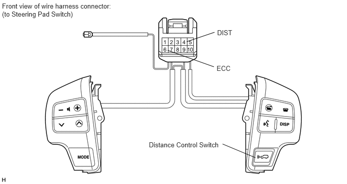
E149031E02
3.075,2.922 4.572,3.082 1.496,0.160 10 Distance Control Switch 4.596,2.983 5.275,3.267 false 4.474,1.329 4.810,1.484 0.336,0.156 10 ECC 3.463,1.043 4.418,1.384 false 4.485,0.598 4.843,0.767 0.357,0.170 10 DIST 3.856,0.863 4.43,0.668 false 0.042,0.037 2.400,0.388 2.357,0.351 10 Front view of wire harness connector: (to Steering Pad Switch)


b.

Measure the resistance according to the value(s) in the table below.

Standard Resistance:
Tester Connection Switch Condition Specified Condition
4 (DIST) - 6 (ECC) Distance control switch on (pushed) Below 1 Ω
Distance control switch off (pushed again) 1 MΩ or higher


OK

4.INSPECT SPIRAL CABLE

NG

4.INSPECT SPIRAL CABLE
a.

Check the spiral cable and connector for scratches, cracks, dents and chips. If any defects are found, replace the spiral cable with a new one.
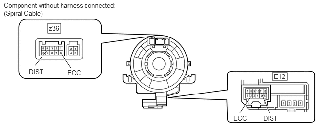
E349662E01
1.021,0.5 1.292,0.708 0.271,0.208 5.802,1.552 6.125,1.719 0.323,0.167 0.75,1.396 1,1.083 true 1.51,1.448 1.313,1.156 true 5.115,2.417 5.333,2.083 true 5.75,2.417 5.573,1.99 true 1.042,0.521 1.5,0.719 0.458,0.198 10 false z36 0.615,1.448 1.073,1.646 0.458,0.198 10 false DIST 1.438,1.469 1.896,1.667 0.458,0.198 10 false ECC 5.844,1.552 6.302,1.75 0.458,0.198 10 false E12 4.979,2.448 5.438,2.646 0.458,0.198 10 false ECC 5.615,2.448 6.073,2.646 0.458,0.198 10 false DIST 0.083,0.031 2.75,0.583 2.667,0.552 10 false Component without harness connected: (Spiral Cable)


b.

Check the spiral cable.

i.

Set the spiral cable to the center position (See page Vehicle Interior>SUPPLEMENTAL RESTRAINT SYSTEMS>SPIRAL CABLE>INSTALLATION).


ii.

After setting the spiral cable to the center position, rotate the spiral cable 2.5 times clockwise, and measure the resistance according to the value(s) in the table below. Then rotate the spiral cable 5 times counterclockwise, and measure the resistance according to the value(s) in the table below.

Standard Resistance:
Tester Connection Condition Specified Condition
z36-4 (DIST) - E12-11 (DIST) Always Below 1 Ω
z36-6 (ECC) - E12-2 (ECC)


iii.

After setting the spiral cable to the center position, rotate the spiral cable 2.5 times clockwise. Then while rotating the spiral cable 5 times counterclockwise, measure the resistance according to the value(s) in the table below.

NOTICE:

As the spiral cable may break, do not rotate the spiral cable more than the specified amount.


Standard Resistance:
Tester Connection Condition Specified Condition
z36-4 (DIST) - E12-11 (DIST) Always Below 1 Ω
z36-6 (ECC) - E12-2 (ECC)


OK

5.CHECK HARNESS AND CONNECTOR (SPIRAL CABLE - DISTANCE CONTROL ECU AND BODY GROUND)

NG

5.CHECK HARNESS AND CONNECTOR (SPIRAL CABLE - DISTANCE CONTROL ECU AND BODY GROUND)
a.
U165815E01
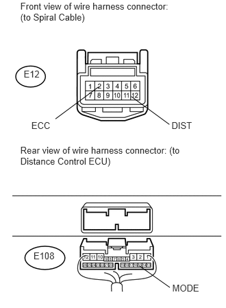
0.309,0.011 2.715,0.523 2.406,0.512 10 Front view of wire harness connector: (to Spiral Cable) 0.309,2.193 2.715,2.858 2.406,0.665 10 Rear view of wire harness connector: (to Distance Control ECU) 0.36,1.037 0.655,1.235 0.295,0.198 10 E12 0.51,3.806 0.870,3.953 0.360,0.147 10 E108 2.62,4.292 3.074,4.452 0.454,0.159 10 MODE 2.609,1.828 2.952,1.987 0.343,0.159 10 DIST 1.996,1.465 2.576,1.889 false 0.477,1.828 0.821,1.987 0.343,0.159 10 ECC 1.501,1.317 0.843,1.805 false 2.119,4.037 2.583,4.364 false

Disconnect the E108 distance control ECU connector.


b.

Disconnect the E12 spiral cable connector.


c.

Measure the resistance according to the value(s) in the table below.

Standard Resistance:
Tester Connection Condition Specified Condition
E12-2 (ECC) - Body ground Always Below 1 Ω
E12-11 (DIST) - E108-16 (MODE) Always Below 1 Ω
E12-11 (DIST) - Body ground Always 10 kΩ or higher


OK

NG

REPAIR OR REPLACE HARNESS OR CONNECTOR