CLUTCH CLUTCH PEDAL(for LHD) INSTALLATION
PROCEDURE

 31353
1.INSTALL CLUTCH PEDAL SPRING HOLDER
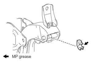
Apply MP grease to the contact surface of the clutch pedal spring holder.
Install the clutch pedal spring holder to the clutch pedal support.
31453B
2.INSTALL CLUTCH MASTER CYLINDER PUSH ROD CLEVIS BUSH
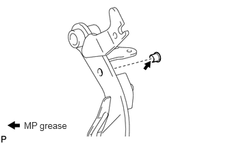
Apply MP grease to the inside of a new clevis bush.
Install the clevis bush to the clutch pedal.
- HINT:
-
Install the clevis bush from the right side of the vehicle.
31301P
3.INSTALL CLUTCH PEDAL TURNOVER BUSH
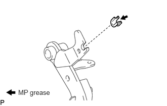
Apply MP grease to the inside of the clutch pedal turnover bush.
Install the clutch pedal turnover bush to the clutch pedal.
31301S
4.INSTALL NO. 2 CLUTCH PEDAL CUSHION
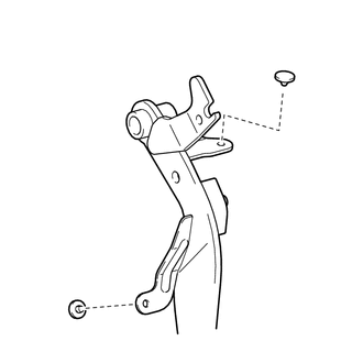
Install the 2 clutch pedal cushions to the clutch pedal.
31301C
5.INSTALL CLUTCH PEDAL BUSH
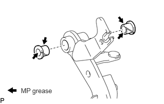
Apply MP grease to the inside and outside of 2 new bushes.
Install the 2 bushes to the clutch pedal.
31324A
6.INSTALL CLUTCH PEDAL SHAFT COLLAR
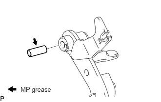
Apply MP grease to the clutch pedal shaft collar.
Install the clutch pedal shaft collar to the clutch pedal.
31321
7.INSTALL CLUTCH PEDAL PAD
Install the clutch pedal pad to the clutch pedal.
31301
8.INSTALL CLUTCH PEDAL SUB-ASSEMBLY
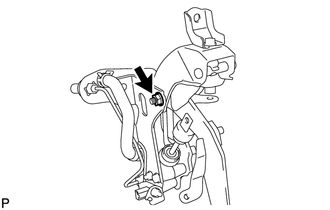
Install the clutch pedal to the clutch pedal support with the nut, washer and bolt.
- Torque:
- 34 N*m (350 kgf*cm, 25 ft.*lbf)
- HINT:
-
Install the bolt from the right side of the vehicle.
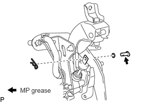
Apply MP grease to the contact surface of the clevis pin and clevis bush.
Install the wave washer to the clevis pin.
Connect the clevis of the master cylinder to the clutch pedal with the clevis pin.
Install a new clip to the clevis pin.
31301A
9.INSTALL CLUTCH PEDAL SPRING
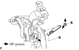
Apply MP grease to the inside and outside of the spacer and pin of the clutch pedal support.
Install the spacer to the spring.
Install the spring to the clutch pedal support with 2 new E-rings.
31301R
10.INSTALL TURNOVER SPRING
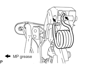
Apply MP grease to the contact surfaces of the spring holder, clutch pedal and spring.
Move the pedal to the full stroke position.
Install the spring to the clutch pedal and spring holder.
11.INSTALL CLUTCH PEDAL SUPPORT ASSEMBLY WITH CLUTCH MASTER CYLINDER
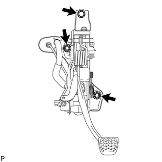
Install the clutch pedal support with clutch master cylinder with the bolt and 2 nuts.
- Torque:
- for bolt : 18 N*m (184 kgf*cm, 13 ft.*lbf)
- for nut : 14 N*m (145 kgf*cm, 10 ft.*lbf)
Connect the clutch start switch connector.
w/ Cruise Control System:
Connect the clutch switch connector.
31481
12.CONNECT CLUTCH MASTER CYLINDER TO FLEXIBLE HOSE TUBE AND CLUTCH RESERVOIR TUBE
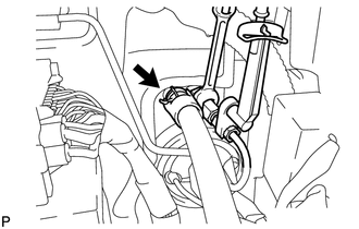
Using a union nut wrench, connect the flexible hose tube.
- Torque:
- 15 N*m (155 kgf*cm, 11 ft.*lbf)
- NOTICE:
-
Use the formula to calculate special torque values for situations where a union nut wrench is combined with a torque wrench (See page General>INTRODUCTION>REPAIR INSTRUCTION>PRECAUTION).
Connect the clutch reservoir tube with a new clip.
82733A
13.INSTALL MAIN BODY ECU (COWL SIDE JUNCTION BLOCK LH)
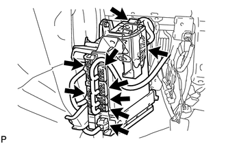
Connect the 9 ECU connectors.
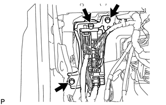
Install the ECU with the 3 bolts.
- Torque:
- 8.0 N*m (82 kgf*cm, 71 in.*lbf)
14.FILL RESERVOIR WITH BRAKE FLUID
15.BLEED CLUTCH LINE
31301
16.INSPECT AND ADJUST CLUTCH PEDAL SUB-ASSEMBLY
17.CHECK FLUID LEVEL IN RESERVOIR
18.INSPECT FOR CLUTCH FLUID LEAK
55303B
19.INSTALL LOWER INSTRUMENT PANEL SUB-ASSEMBLY (w/o Driver Side Knee Airbag)
73900
20.INSTALL DRIVER SIDE KNEE AIRBAG ASSEMBLY (w/ Driver Side Knee Airbag)
55446A
21.INSTALL NO. 1 SWITCH HOLE BASE
55432D
22.INSTALL LOWER NO. 1 INSTRUMENT PANEL FINISH PANEL
62112
23.INSTALL COWL SIDE TRIM BOARD LH
55606
24.INSTALL NO. 1 INSTRUMENT PANEL UNDER COVER SUB-ASSEMBLY (w/ Floor Under Cover)
67914B
25.INSTALL FRONT DOOR SCUFF PLATE LH
55475A
26.INSTALL NO. 2 INSTRUMENT CLUSTER FINISH PANEL GARNISH
55474C
27.INSTALL NO. 1 INSTRUMENT CLUSTER FINISH PANEL GARNISH
55318C
28.INSTALL INSTRUMENT SIDE PANEL LH
55403C
29.INSTALL LOWER INSTRUMENT PANEL PAD SUB-ASSEMBLY LH
55449C
30.INSTALL NO. 2 INSTRUMENT PANEL FINISH PANEL CUSHION