SUSPENSION CONTROL SUSPENSION CONTROL SYSTEM(w/ KDSS) BLEEDING
PROCEDURE

 1. BLEED AIR FROM SUSPENSION FLUID
- CAUTION:
- ·
Make sure to check the pipe connections and whether or not any hydraulic circuit parts are damaged before performing work, as the hydraulic circuits become highly pressurized during air bleeding.
·The pipes become highly pressurized when bleeding air. If a fluid leak is discovered, immediately release the pressure and repair the fluid leak as there is danger involved.
- HINT:
-
When bleeding air, approximately 6 liters of fluid is needed.
Remove the stabilizer control valve protector (See page Suspension>SUSPENSION CONTROL>STABILIZER CONTROL VALVE(w/ KDSS)>REMOVAL).
Remove the rear stabilizer control tube insulator (See page Suspension>REAR SUSPENSION>REAR STABILIZER BAR(w/ KDSS)>REMOVAL).
Remove the stabilizer control tube protector (See page Suspension>FRONT SUSPENSION>FRONT STABILIZER BAR(w/ KDSS)>REMOVAL).
Check the pipe connections and whether or not any hydraulic circuit parts are damaged.
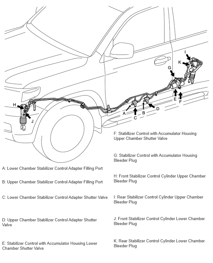
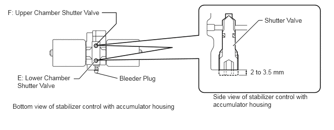
Using a 5 mm socket hexagon wrench, loosen the shutter valves (E, F) of the stabilizer control with accumulator housing 2.0 to 3.5 turns.
- NOTICE:
- ·
When loosening the shutter valves (E, F), make sure that the end protrudes 2 to 3.5 mm (0.0787 to 0.137 in.) from the surface of the block, and do not turn the shutter valve any further.
·Do not remove the shutter valves.
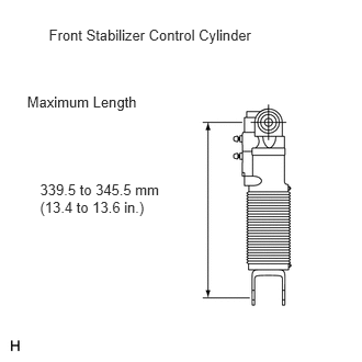
Disconnect the front stabilizer control arm and front stabilizer link LH, and set the front stabilizer control cylinder to the maximum length.
- NOTICE:
-
Set the front stabilizer control cylinder to the maximum length to completely bleed the air.
- HINT:
-
Refer to the following procedures to disconnect the front stabilizer control arm and front stabilizer link LH (See page Suspension>FRONT SUSPENSION>FRONT STABILIZER BAR(w/ KDSS)>REMOVAL).
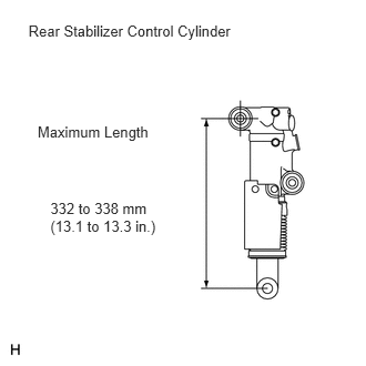
Disconnect the rear stabilizer bar and rear stabilizer link, and set the rear stabilizer control cylinder to the maximum length.
- NOTICE:
-
Set the rear stabilizer control cylinder to the maximum length to completely bleed the air.
- HINT:
-
Refer to the following procedures to disconnect the rear stabilizer bar and rear stabilizer link (See page Suspension>REAR SUSPENSION>REAR STABILIZER BAR(w/ KDSS)>REMOVAL).
Add new fluid to SST (high pressure oil pump), and bleed air from the SST hoses.
- SST
- 09760-60020
- Fluid:
Suspension fluid AHC
- NOTICE:
-
If air is not bled from the hoses, the air will mix into the hydraulic circuit.
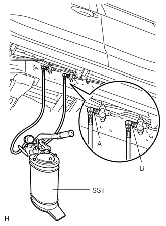
Remove the service valve caps of the stabilizer control adapter filling ports (A, B). Then put fluid into SST (high pressure oil pump), and connect SST to the stabilizer control adapter filling ports.
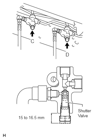
Loosen the stabilizer control adapter shutter valves (C, D) 1.5 to 2.5 turns.
- NOTICE:
- ·
When loosening a shutter valve, make sure that the end of the part that is protruding is 15 to 16.5 mm (0.591 to 0.649 in.) from the surface of the block, and do not turn the shutter valve any further.
·Do not remove the shutter valves.
Using SST (high pressure oil pump), add fluid.
- CAUTION:
-
If a fluid leak is discovered, immediately release the pressure and repair the fluid leak as there is danger involved due to high pressure.
- NOTICE:
-
Do not apply 8 MPa (81.6 kgf/cm2, 1160 psi) or more of pressure, as the accumulator may be damaged.
Pump SST (high pressure oil pump) to add fluid until the pressure reaches 5 MPa (51.0 kgf/cm2, 725 psi).*1
Check for fluid leaks from the pipe connections and hydraulic circuit parts.
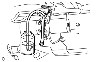
Add fluid to the stabilizer control with accumulator housing.*2
Loosen the bleeder plug (G) of the stabilizer control with accumulator housing.
Pump SST (high pressure oil pump) and maintain a pressure of approximately 3 MPa (30.6 kgf/cm2, 435 psi) until air stops coming out.
Tighten the bleeder plug (G) of the stabilizer control with accumulator housing.
- Torque:
- 8.3 N*m (85 kgf*cm, 73 in.*lbf)
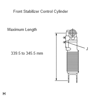
Check that the front stabilizer control cylinder is at the maximum length (339.5 to 345.5 mm (13.4 to 13.6 in.)).
Add fluid to the lower chamber of the front stabilizer control cylinder.*3
Pump SST (high pressure oil pump) to add fluid until the pressure reaches 5 MPa (51.0 kgf/cm2, 725 psi).
Loosen the lower chamber bleeder plug (J) of the front stabilizer control cylinder.
Pump SST (high pressure oil pump) and maintain a pressure of approximately 3 MPa (30.6 kgf/cm2, 435 psi) until air stops coming out.
Tighten the lower chamber bleeder plug (J) of the front stabilizer control cylinder.
- Torque:
- 8.3 N*m (85 kgf*cm, 73 in.*lbf)
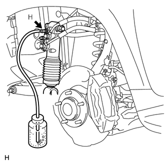
Add fluid to the upper chamber of the front stabilizer control cylinder.*4
Pump SST (high pressure oil pump) to add fluid until the pressure reaches 5 MPa (51.0 kgf/cm2, 725 psi).
Loosen the upper chamber bleeder plug (H) of the front stabilizer control cylinder.
Pump SST (high pressure oil pump) and maintain a pressure of approximately 3 MPa (30.6 kgf/cm2, 435 psi) until air stops coming out.
Tighten the upper chamber bleeder plug (H) of the front stabilizer control cylinder.
- Torque:
- 8.3 N*m (85 kgf*cm, 73 in.*lbf)
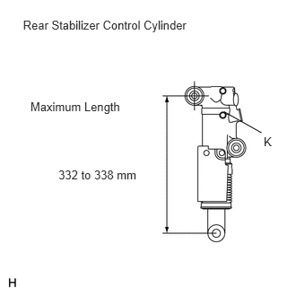
Check that the rear stabilizer control cylinder is at the maximum length (332 to 328 mm (13.1 to 13.3 in.)).
Add fluid to the lower chamber of the rear stabilizer control cylinder.*5
Pump SST (high pressure oil pump) to add fluid until the pressure reaches 5 MPa (51.0 kgf/cm2, 725 psi).
Loosen the lower chamber bleeder plug (K) of the rear stabilizer control cylinder.
Pump SST (high pressure oil pump) and maintain a pressure of approximately 3 MPa (30.6 kgf/cm2, 435 psi) until air stops coming out.
Tighten the lower chamber bleeder plug (K) of the rear stabilizer control cylinder.
- Torque:
- 8.3 N*m (85 kgf*cm, 73 in.*lbf)
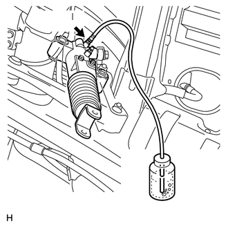
Add fluid to the upper chamber of the rear stabilizer control cylinder.*6
Pump SST (high pressure oil pump) to add fluid until the pressure reaches 5 MPa (51.0 kgf/cm2, 725 psi).
Loosen the upper chamber bleeder plug (I) of the rear stabilizer control cylinder.
Pump SST (high pressure oil pump) and maintain a pressure of approximately 3 MPa (30.6 kgf/cm2, 435 psi) until air stops coming out.
Tighten the upper chamber bleeder plug (I) of the rear stabilizer control cylinder.
- Torque:
- 8.3 N*m (85 kgf*cm, 73 in.*lbf)
Repeat procedures *1 to *6 until the air in the fluid is gone.
Using SST (high pressure oil pump), bleed the air.
- NOTICE:
- ·
Make sure to apply 7 MPa (71.4 kgf/cm2, 1015 psi) of pressure to all parts. If the pressure is low, the air may not be released.
·Do not apply 8 MPa (81.6 kgf/cm2, 1160 psi) or more of pressure, as the accumulator may be damaged.
Bleed air from the stabilizer control with accumulator housing.
Pump SST (high pressure oil pump) to apply 7 MPa (71.4 kgf/cm2, 1015 psi) of pressure.
Loosen the bleeder plug (G) of the stabilizer control with accumulator housing to bleed the air.
Tighten the bleeder plug so pressure can be applied and repeat until the air in the fluid is gone.
Tighten the bleeder plug (G) of the stabilizer control with accumulator housing.
- Torque:
- 8.3 N*m (85 kgf*cm, 73 in.*lbf)
Bleed air from the upper chamber of the front stabilizer control cylinder.
Pump SST (high pressure oil pump) to apply 7 MPa (71.4 kgf/cm2, 1015 psi) of pressure.
Loosen the upper chamber bleeder plug (H) of the front stabilizer control cylinder to bleed the air.
Tighten the bleeder plug so pressure can be applied and repeat until the air in the fluid is gone.
Tighten the upper chamber bleeder plug (H) of the front stabilizer control cylinder.
- Torque:
- 8.3 N*m (85 kgf*cm, 73 in.*lbf)
Bleed air from the upper chamber of the rear stabilizer control cylinder.
Pump SST (high pressure oil pump) to apply 7 MPa (71.4 kgf/cm2, 1015 psi) of pressure.
Loosen the upper chamber bleeder plug (I) of the rear stabilizer control cylinder to bleed the air.
Tighten the bleeder plug so pressure can be applied and repeat until the air in the fluid is gone.
Tighten the upper chamber bleeder plug (I) of the rear stabilizer control cylinder.
- Torque:
- 8.3 N*m (85 kgf*cm, 73 in.*lbf)
Bleed air from the lower chamber of the front stabilizer control cylinder.
Pump SST (high pressure oil pump) to apply 7 MPa (71.4 kgf/cm2, 1015 psi) of pressure.
Loosen the lower chamber bleeder plug (J) of the front stabilizer control cylinder to bleed the air.
Tighten the bleeder plug so pressure can be applied and repeat until the air in the fluid is gone.
Tighten the lower chamber bleeder plug (J) of the front stabilizer control cylinder.
- Torque:
- 8.3 N*m (85 kgf*cm, 73 in.*lbf)
Bleed air from the lower chamber of the rear stabilizer control cylinder.
Pump SST (high pressure oil pump) to apply 7 MPa (71.4 kgf/cm2, 1015 psi) of pressure.
Loosen the lower chamber bleeder plug (K) of the rear stabilizer control cylinder to bleed the air.
Tighten the bleeder plug so pressure can be applied and repeat until the air in the fluid is gone.
Tighten the lower chamber bleeder plug (K) of the rear stabilizer control cylinder.
- Torque:
- 8.3 N*m (85 kgf*cm, 73 in.*lbf)
Connect the front stabilizer control arm to the front stabilizer link LH and the rear stabilizer bar to the rear stabilizer link.
- HINT:
- ·
For the front side, refer to the following procedures (See page Suspension>FRONT SUSPENSION>FRONT STABILIZER BAR(w/ KDSS)>INSTALLATION).
·For the rear side, refer to the following procedures (See page Suspension>REAR SUSPENSION>REAR STABILIZER BAR(w/ KDSS)>INSTALLATION).
With all wheels on the ground, apply the specified amount of pressure using SST. Maintain this pressure for 2 to 3 minutes to stabilize the pressure.
- NOTICE:
- ·
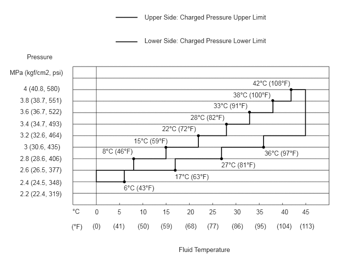
Refer to the Temperature Management Chart when Filling Fluid, as the specified pressure changes according to the fluid temperature.
·Perform the inspection with the vehicle load completely on the suspension.
- HINT:
- ·
Perform this step with the fuel tank full.
·If there are any parts installed to the vehicle which place any unbalanced load on the left or right side of the vehicle, remove them.
- Standard Fluid Pressure:
Condition Specified Pressure Fluid temperature is 20°C (68°F) 2.8 to 3 MPa (28.6 to 30.6 kgf/cm2, 406 to 435 psi)
Tighten the shutter valves (C, D) of the stabilizer control adapter.
- Torque:
- 14 N*m (140 kgf*cm, 10 ft.*lbf)
Remove SST (high pressure oil pump) from the stabilizer control adapter (A, B).
- NOTICE:
-
Make sure that no pressure is applied to SST (high pressure oil pump).
Install the service valve caps to the stabilizer control adapter.
- Torque:
- 0.6 N*m (6.0 kgf*cm, 5.0 in.*lbf)
With all wheels on the ground, check that the difference in height between the left and right side of the vehicle is within 15 mm (0.591 in.).
With all wheels on the ground, tighten the shutter valves (E, F) of the stabilizer control with accumulator housing with a 5 mm socket hexagon wrench.
- Torque:
- 14 N*m (140 kgf*cm, 10 ft.*lbf)
- NOTICE:
-
Perform the inspection with the vehicle load completely on the suspension.
- HINT:
- ·
Perform this step with the fuel tank full.
·If there are any parts installed to the vehicle which place any unbalanced load on the left or right side of the vehicle, remove them.
Inspect for suspension fluid leak (See page Suspension>SUSPENSION CONTROL>SUSPENSION CONTROL SYSTEM (w/ KDSS)>ON-VEHICLE INSPECTION).
Install the stabilizer control valve protector.
- Torque:
- 18 N*m (184 kgf*cm, 13 ft.*lbf)
Install the rear stabilizer control tube insulator.
- Torque:
- 18 N*m (184 kgf*cm, 13 ft.*lbf)
Install the stabilizer control tube protector.
- Torque:
- 15 N*m (153 kgf*cm, 11 ft.*lbf)
2. TEMPERATURE MANAGEMENT CHART WHEN FILLING FLUID