BRAKE CONTROL / DYNAMIC CONTROL SYSTEMS VEHICLE STABILITY CONTROL SYSTEM VSC OFF Indicator Light Remains ON
DESCRIPTION
w/o Entry and Start System:
Operation of the VSC OFF switch changes the vehicle between normal mode, TRC OFF mode and VSC OFF mode. During normal mode, pressing the VSC OFF switch for a short amount of time changes vehicle to TRC OFF mode. When the vehicle is stopped, pressing the VSC OFF switch for 3 seconds or more changes the vehicle to VSC OFF mode.
w/ Entry and Start System:
Operation of the VSC OFF switch (integration control and panel assembly) changes the vehicle between normal mode, TRC OFF mode and VSC OFF mode. During normal mode, pressing the VSC OFF switch (integration control and panel assembly) for a short amount of time changes vehicle to TRC OFF mode. When the vehicle is stopped, pressing the VSC OFF switch (integration control and panel assembly) for 3 seconds or more changes the vehicle to VSC OFF mode.
When the transfer is in L4, the VSC OFF indicator light turns on.
WIRING DIAGRAM
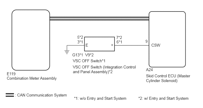
CAUTION / NOTICE / HINT
- NOTICE:
- ·
After replacing the master cylinder solenoid, perform zero point calibration and store the system information (See page Brake>BRAKE CONTROL / DYNAMIC CONTROL SYSTEMS>VEHICLE STABILITY CONTROL SYSTEM>CALIBRATION).
·As there may be malfunctions in the transfer system related to when the transfer operates in L4, check the transfer system first (See page Drivetrain>JF2A (TRANSFER / 4WD / AWD)>TRANSFER SYSTEM>HOW TO PROCEED WITH TROUBLESHOOTING).
PROCEDURE
OK
NG
A
B
C
D
E
A
B
C
D
E
OK
(See pageVehicle Interior>METER / GAUGE / DISPLAY>METER / GAUGE SYSTEM>HOW TO PROCEED WITH TROUBLESHOOTING)
NG
A
B
(See pageBrake>BRAKE CONTROL / DYNAMIC CONTROL SYSTEMS>VSC OFF SWITCH(w/o Entry and Start System)>REMOVAL)
C
(See pageBrake>BRAKE CONTROL / DYNAMIC CONTROL SYSTEMS>VSC OFF SWITCH(w/ Entry and Start System)>REMOVAL)
A
B
C