BRAKE CONTROL / DYNAMIC CONTROL SYSTEMS ANTI-LOCK BRAKE SYSTEM C1251 Open in Pump Motor Circuit
DESCRIPTION
The motor relay (semiconductor relay) is built into the master cylinder solenoid and drives the pump motor based on a signal from the skid control ECU (master cylinder solenoid).
| DTC Code | DTC Detection Condition | Trouble Area |
|---|---|---|
| C1251 | There is an open in the motor system circuit (motor input circuit). | ·
Pump motor wire harness connection ·
Brake booster with accumulator pump assembly ·
Skid control ECU (Master cylinder solenoid) |
CAUTION / NOTICE / HINT
- NOTICE:
-
After replacing the master cylinder solenoid, perform zero point calibration (See page Brake>BRAKE CONTROL / DYNAMIC CONTROL SYSTEMS>ANTI-LOCK BRAKE SYSTEM>CALIBRATION).
- HINT:
-
Remove the hydraulic brake booster assembly before the inspection (for LHD: See page Brake>BRAKE SYSTEM (OTHER)>HYDRAULIC BRAKE BOOSTER(for LHD)>ON-VEHICLE INSPECTION, for RHD: See page Brake>BRAKE SYSTEM (OTHER)>HYDRAULIC BRAKE BOOSTER(for RHD)>ON-VEHICLE INSPECTION).
PROCEDURE
Remove the hydraulic brake booster assembly (for LHD: See page Brake>BRAKE SYSTEM (OTHER)>HYDRAULIC BRAKE BOOSTER(for LHD)>REMOVAL, for RHD: See page Brake>BRAKE SYSTEM (OTHER)>HYDRAULIC BRAKE BOOSTER(for RHD)>REMOVAL).
Check the tightening torque of the 2 screws which secure the wire harness connecting the master cylinder solenoid and brake booster with accumulator pump assembly (for LHD: See page Brake>BRAKE SYSTEM (OTHER)>HYDRAULIC BRAKE BOOSTER(for LHD)>REASSEMBLY, for RHD: See page Brake>BRAKE SYSTEM (OTHER)>HYDRAULIC BRAKE BOOSTER(for RHD)>REASSEMBLY).
- OK:
The harness is tightened to the specified torque.
OK
NG
Using a screwdriver, remove the 2 screws and pull out the wire harness from the master cylinder solenoid.
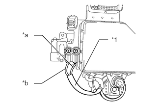
Measure the resistance according to the value(s) in the table below.
- Standard Resistance:
Tester Connection Condition Specified Condition Red wire terminal - Black wire terminal Always Below 2 Ω
| *1 | Pump motor wire harness |
| *a | Red wire |
| *b | Black wire |
- HINT:
- Refer to the brake booster with accumulator pump assembly installation procedures:·
for LHD (See page Brake>BRAKE SYSTEM (OTHER)>HYDRAULIC BRAKE BOOSTER(for LHD)>DISASSEMBLY)
·for RHD (See page Brake>BRAKE SYSTEM (OTHER)>HYDRAULIC BRAKE BOOSTER(for RHD)>DISASSEMBLY)
OK
NG
Reassemble the hydraulic brake booster assembly (for LHD: See page Brake>BRAKE SYSTEM (OTHER)>HYDRAULIC BRAKE BOOSTER(for LHD)>REASSEMBLY, for RHD: See page Brake>BRAKE SYSTEM (OTHER)>HYDRAULIC BRAKE BOOSTER(for RHD)>REASSEMBLY).
Install the hydraulic brake booster assembly (for LHD: See page Brake>BRAKE SYSTEM (OTHER)>HYDRAULIC BRAKE BOOSTER(for LHD)>INSTALLATION, for RHD: See page Brake>BRAKE SYSTEM (OTHER)>HYDRAULIC BRAKE BOOSTER(for RHD)>INSTALLATION).
Clear the DTCs (See page Brake>BRAKE CONTROL / DYNAMIC CONTROL SYSTEMS>ANTI-LOCK BRAKE SYSTEM>DTC CHECK / CLEAR).
Turn the ignition switch off.
Check if the same DTC is output (See page Brake>BRAKE CONTROL / DYNAMIC CONTROL SYSTEMS>ANTI-LOCK BRAKE SYSTEM>DTC CHECK / CLEAR).
| Result | Proceed to |
|---|---|
| DTC is not output | A |
| DTC is output (for LHD) | B |
| DTC is output (for RHD) | C |
A
(See pageGeneral>INTRODUCTION>HOW TO TROUBLESHOOT ECU CONTROLLED SYSTEMS>HOW TO PROCEED WITH TROUBLESHOOTING)
B
C