STEERING COLUMN STEERING COLUMN ASSEMBLY(for Power Tilt and Power Telescopic Steering Column) INSTALLATION
CAUTION / NOTICE / HINT
- HINT:
- ·
Use the same procedure for RHD and LHD vehicles.
·The procedure listed below is for LHD vehicles.
PROCEDURE

 45203A
1.CONNECT NO. 2 STEERING INTERMEDIATE SHAFT
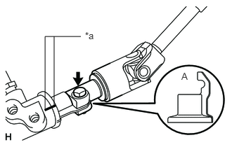
Align the part of the dust cover labeled A with the No. 2 steering intermediate shaft, and install the No. 2 steering intermediate shaft assembly to the steering link assembly.
| *a | Matchmark |
Install the bolt.
- Torque:
- 35 N*m (357 kgf*cm, 26 ft.*lbf)
- NOTICE:
-
Be careful not to damage the dust cover.
45026D
2.INSTALL STEERING COLUMN HOLE COVER SUB-ASSEMBLY (w/ VGRS)
Install the 4 bolts and nut.
- Torque:
- 5.0 N*m (51 kgf*cm, 44 in.*lbf)
- NOTICE:
-
Do not fold back the boot part of the steering hole cover or extend it excessively. if it is extended excessively, return it to its original position.
45026D
3.INSTALL STEERING COLUMN HOLE COVER SUB-ASSEMBLY (w/o VGRS)
Install the 4 bolts and nut.
- Torque:
- 5.0 N*m (51 kgf*cm, 44 in.*lbf)
- NOTICE:
-
Do not fold back the boot part of the steering hole cover or extend it excessively. if it is extended excessively, return it to its original position.
- HINT:
-
Install the steering intermediate shaft assembly from the inside of the vehicle.
Install the clamp to the steering column hole cover.
45240J
4.CONNECT STEERING ACTUATOR ASSEMBLY
45250
5.INSTALL STEERING COLUMN ASSEMBLY
Install the 4 nuts and steering column.
- Torque:
- 26 N*m (265 kgf*cm, 19 ft.*lbf)
w/ VGRS:
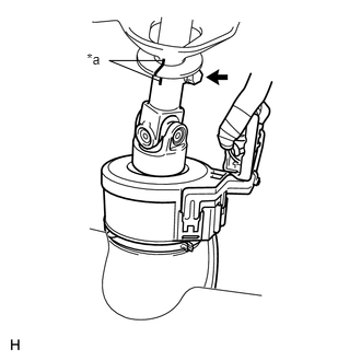
Align the matchmarks on the steering column and steering actuator assembly.
| *a | Matchmark |
Install the bolt.
- Torque:
- 35 N*m (357 kgf*cm, 26 ft.*lbf)
w/o VGRS:
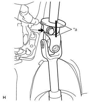
Align the matchmarks on the steering column and steering intermediate shaft.
| *a | Matchmark |
Install the bolt.
- Torque:
- 35 N*m (357 kgf*cm, 26 ft.*lbf)
87201F
6.INSTALL NO. 3 AIR DUCT SUB-ASSEMBLY
7.INSTALL WIRE HARNESS PROTECTOR AND WIRE HARNESS
Attach the 2 claws and 2 harness clamps and connect the wire harness protector and wire harness.
73900
8.INSTALL LOWER NO. 1 INSTRUMENT PANEL AIRBAG ASSEMBLY (w/ Driver Side Knee Airbag)
55303B
9.INSTALL LOWER INSTRUMENT PANEL SUB-ASSEMBLY (w/o Driver Side Knee Airbag)
10.INSTALL COMBINATION SWITCH ASSEMBLY WITH SPIRAL CABLE SUB-ASSEMBLY
Attach the 3 claws to install the combination switch assembly with spiral cable sub-assembly to the steering column assembly.
Connect connectors to the combination switch assembly with spiral cable sub-assembly.
45286B
11.INSTALL UPPER STEERING COLUMN COVER
Attach the 2 guide pin and claw.
Attach the 4 clips and 2 claws to install the upper steering column cover onto the meter hood spacer.
12.INSTALL LOWER STEERING COLUMN COVER
Attach the 4 claws to install the lower steering column cover.
- NOTICE:
-
Do not damage the tilt and telescopic switch.
Install the 3 screws.
- Torque:
- 1.5 N*m (15 kgf*cm, 13 in.*lbf)
45100
13.INSTALL STEERING WHEEL ASSEMBLY
14.CHECK FRONT WHEELS FACING STRAIGHT AHEAD
15.INSTALL FRONT WHEEL
16.CONNECT CABLE TO NEGATIVE BATTERY TERMINAL
- NOTICE:
- ·
Reset the AUTO TILT AWAY function setting to the previous condition by changing the customize parameter (See page Steering>STEERING COLUMN>POWER TILT AND POWER TELESCOPIC STEERING COLUMN SYSTEM>CUSTOMIZE PARAMETERS).
·When disconnecting the cable, some systems need to be initialized after the cable is reconnected (See page General>INTRODUCTION>REPAIR INSTRUCTION>INITIALIZATION).
17.INSPECT SRS WARNING LIGHT
18.PERFORM VARIABLE GEAR RATIO STEERING SYSTEM CALIBRATION (w/ VGRS)