Home › Power Source / Network › NETWORKING › CAN COMMUNICATION SYSTEM(for LHD) › 2014.08–2015.08
RM2660E _57 Power Source / Network _052837 NETWORKING _0255533 CAN COMMUNICATION SYSTEM(for LHD) J

NETWORKING  CAN COMMUNICATION SYSTEM(for LHD)  Open in One Side of CAN Branch Line  


DESCRIPTION

If 2 or more ECUs and/or sensors do not appear on the intelligent tester "Bus Check" screen, one side of the CAN branch wire may be open (One side of the CANH [branch wire]/CANL [branch wire] of the ECU and/or sensor is open).

Symptom Trouble Area
2 or more ECUs and/or sensors do not appear on the intelligent tester "Bus Check" screen.
·

One side of CAN branch wire is open

·

Center airbag sensor assembly*1

·

Headlight swivel ECU assembly*2

·

Multi-media module receiver assembly*3

·

Air conditioning amplifier assembly

·

Main body ECU (cowl side junction block LH)

·

Network gateway ECU*4

·

4WD control ECU*5

·

Clearance warning ECU assembly*5, *6

·

Master cylinder solenoid (skid control ECU)*5


*1: w/ Airbag System

*2: w/ Dynamic Headlight Auto Leveling

*3: w/ Navigation System

*4: w/ Network Gateway ECU

*5: w/o Network Gateway ECU

*6: w/ TOYOTA Parking Assist-sensor System and w/o Side Monitor System


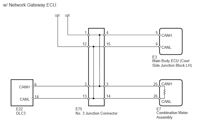
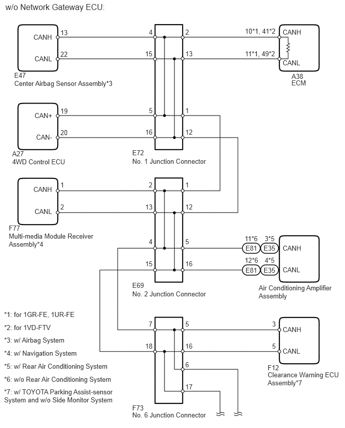
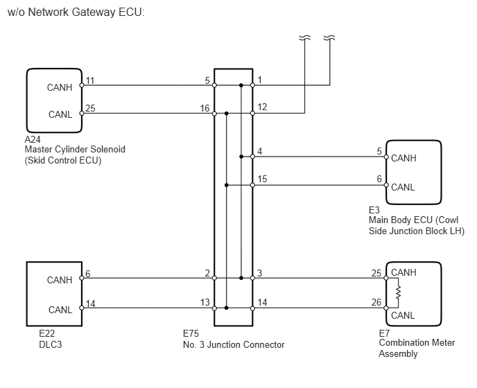
WIRING DIAGRAM
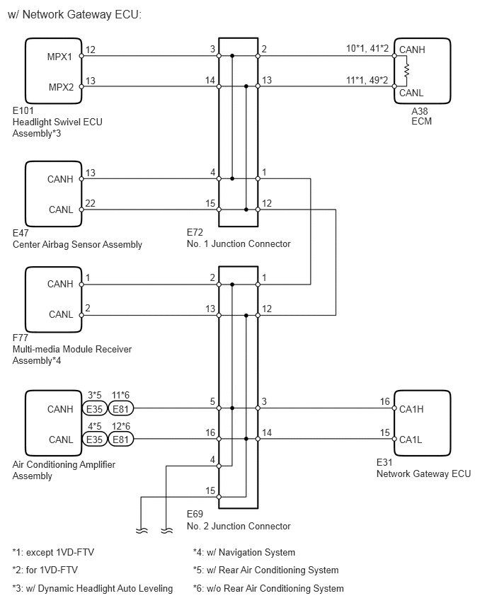
C258823E01
6.055,1.693 6.429,1.840 0.374,0.147 10 ECM 2.748,3.503 4.370,3.660 1.622,0.158 10 No. 1 Junction Connector 2.748,3.33 3.038,3.511 0.290,0.181 10 E72 2.748,7.657 4.370,7.814 1.622,0.158 10 No. 2 Junction Connector 2.748,7.484 3.038,7.665 0.290,0.181 10 E69 0.114,0.108 2.579,0.288 2.465,0.180 12 w/ Network Gateway ECU: 5.873,0.643 6.338,0.785 0.465,0.141 10 CANH 6.057,1.555 6.370,1.698 0.313,0.143 10 A38 3.85,0.639 4.050,0.810 0.200,0.170 10 2 3.85,1.096 4.050,1.266 0.200,0.170 10 13 3.85,2.447 4.050,2.617 0.200,0.170 10 1 3.85,2.903 4.050,3.073 0.200,0.170 10 12 3.85,3.998 4.050,4.169 0.200,0.170 10 1 3.85,4.455 4.050,4.625 0.200,0.170 10 12 3.09,3.998 3.190,4.169 0.100,0.170 10 2 3.018,4.455 3.190,4.625 0.172,0.170 10 13 3.85,5.827 4.050,5.997 0.200,0.170 10 3 3.85,6.283 4.050,6.453 0.200,0.170 10 14 5.587,5.827 5.764,5.997 0.177,0.170 10 16 5.587,6.283 5.764,6.453 0.177,0.170 10 15 3.09,5.827 3.190,5.997 0.100,0.170 10 5 3.018,6.283 3.190,6.453 0.172,0.170 10 16 5.873,1.283 6.338,1.425 0.465,0.141 10 CANL 0.184,1.708 1.583,2.012 1.399,0.304 10 Headlight Swivel ECU Assembly*3 0.184,1.542 0.528,1.711 0.345,0.169 10 E101 3.092,0.639 3.191,0.810 0.098,0.170 10 3 3.014,1.096 3.190,1.266 0.176,0.170 10 14 1.254,0.651 1.426,0.789 0.172,0.138 10 12 1.254,1.101 1.426,1.239 0.172,0.138 10 13 0.694,0.745 1.113,0.881 0.418,0.137 10 MPX1 0.717,1.194 1.113,1.331 0.396,0.137 10 MPX2 3.094,2.447 3.191,2.617 0.097,0.170 10 4 3.018,2.903 3.190,3.073 0.172,0.170 10 15 0.184,3.515 2.338,3.666 2.155,0.151 10 Center Airbag Sensor Assembly 0.184,3.349 0.487,3.518 0.303,0.169 10 E47 1.254,2.458 1.426,2.596 0.172,0.138 10 13 1.254,2.908 1.426,3.046 0.172,0.138 10 22 0.694,2.552 1.113,2.689 0.418,0.137 10 CANH 0.717,3.001 1.113,3.138 0.396,0.137 10 CANL 0.184,5.056 2.005,5.360 1.821,0.304 10 Multi-media Module Receiver Assembly*4 0.184,4.89 0.487,5.059 0.303,0.169 10 F77 1.254,3.998 1.426,4.136 0.172,0.138 10 1 1.254,4.449 1.426,4.587 0.172,0.138 10 2 0.694,4.092 1.113,4.229 0.418,0.137 10 CANH 0.717,4.541 1.113,4.678 0.396,0.137 10 CANL 5.089,0.621 5.759,0.767 0.670,0.145 10 10*1, 41*2 5.089,1.092 5.759,1.238 0.670,0.145 10 11*1, 49*2 0.18,8.044 1.840,8.191 1.661,0.147 10 *1: except 1VD-FTV 0.18,8.307 1.840,8.454 1.661,0.147 10 *2: for 1VD-FTV 0.18,8.57 2.785,8.717 2.605,0.147 10 *3: w/ Dynamic Headlight Auto Leveling 2.84,8.044 4.416,8.191 1.576,0.147 10 *4: w/ Navigation System 2.84,8.307 5.088,8.454 2.248,0.147 10 *5: w/ Rear Air Conditioning System 2.84,8.57 5.171,8.717 2.332,0.147 10 *6: w/o Rear Air Conditioning System 0.184,6.751 1.790,7.055 1.606,0.304 10 Air Conditioning Amplifier Assembly 1.269,6.386 1.540,6.523 0.270,0.136 10 E35 1.291,6.187 1.518,6.323 0.227,0.136 10 4*5 1.269,5.933 1.540,6.069 0.270,0.136 10 E35 1.291,5.733 1.518,5.869 0.227,0.136 10 3*5 1.657,6.386 1.927,6.523 0.270,0.136 10 E81 1.64,6.187 1.944,6.323 0.303,0.136 10 12*6 1.657,5.933 1.927,6.069 0.270,0.136 10 E81 1.639,5.733 1.945,5.869 0.307,0.136 10 11*6 5.873,5.934 6.291,6.071 0.419,0.137 10 CA1H 5.873,6.383 6.268,6.520 0.396,0.137 10 CA1L 0.694,5.934 1.113,6.071 0.418,0.137 10 CANH 0.717,6.383 1.113,6.520 0.396,0.137 10 CANL 5.54,6.882 7.014,7.024 1.474,0.142 10 Network Gateway ECU 5.54,6.716 5.843,6.885 0.303,0.169 10 E31 3.09,6.677 3.190,6.847 0.100,0.170 10 4 3.018,7.133 3.190,7.303 0.172,0.170 10 15

C258824E01
5.69,4.03 6.890,4.335 1.200,0.305 10 Combination Meter Assembly 2.748,4.055 4.369,4.212 1.622,0.158 10 No. 3 Junction Connector 2.748,3.897 3.037,4.037 0.290,0.140 10 E75 0.113,0.073 2.578,0.253 2.465,0.180 12 w/ Network Gateway ECU: 5.872,2.981 6.337,3.122 0.465,0.141 10 CANH 5.693,3.893 6.005,4.035 0.313,0.143 10 E7 3.864,1.104 4.064,1.274 0.200,0.170 10 4 3.864,1.518 4.064,1.689 0.200,0.170 10 15 3.864,2.986 4.064,3.156 0.200,0.170 10 3 3.864,3.428 4.064,3.599 0.200,0.170 10 14 5.872,3.621 6.337,3.762 0.465,0.141 10 CANL 3.078,1.104 3.176,1.274 0.098,0.170 10 1 3,1.518 3.175,1.689 0.176,0.170 10 12 3.079,2.986 3.176,3.156 0.097,0.170 10 2 3.003,3.428 3.175,3.599 0.172,0.170 10 13 0.585,4.055 0.959,4.206 0.374,0.151 10 DLC3 0.585,3.897 0.888,4.042 0.303,0.144 10 E22 1.254,2.997 1.426,3.135 0.172,0.138 10 6 1.254,3.447 1.426,3.586 0.172,0.138 10 14 0.694,3.091 1.112,3.228 0.418,0.137 10 CANH 0.717,3.54 1.112,3.677 0.396,0.137 10 CANL 5.579,2.986 5.758,3.131 0.179,0.145 10 25 5.579,3.428 5.758,3.574 0.179,0.145 10 26 5.662,1.104 5.759,1.274 0.097,0.170 10 5 5.662,1.518 5.759,1.689 0.097,0.170 10 6 5.872,1.211 6.291,1.348 0.418,0.137 10 CANH 5.872,1.646 6.268,1.783 0.396,0.137 10 CANL 5.54,2.134 7.038,2.439 1.498,0.305 10 Main Body ECU (Cowl Side Junction Block LH) 5.54,1.996 5.843,2.165 0.303,0.169 10 E3

U165282E01
6.054,1.632 6.428,1.780 0.374,0.147 10 ECM 2.748,3.26 4.369,3.417 1.622,0.158 10 No. 1 Junction Connector 2.748,3.087 3.037,3.268 0.290,0.181 10 E72 0.113,0.048 2.578,0.228 2.465,0.180 12 w/o Network Gateway ECU: 5.872,0.583 6.337,0.724 0.465,0.141 10 CANH 6.057,1.495 6.369,1.637 0.313,0.143 10 A38 3.849,0.579 4.049,0.749 0.200,0.170 10 2 3.849,1.035 4.049,1.205 0.200,0.170 10 13 3.849,2.204 4.049,2.374 0.200,0.170 10 1 3.849,2.66 4.049,2.830 0.200,0.170 10 12 2.748,6.01 4.369,6.168 1.622,0.158 10 No. 2 Junction Connector 2.748,5.838 3.037,6.019 0.290,0.181 10 E69 3.849,3.755 4.049,3.926 0.200,0.170 10 1 3.849,4.212 4.049,4.382 0.200,0.170 10 12 3.089,3.755 3.190,3.926 0.100,0.170 10 2 3.017,4.212 3.189,4.382 0.172,0.170 10 13 3.849,4.928 4.049,5.099 0.200,0.170 10 5 3.849,5.385 4.049,5.555 0.200,0.170 10 16 3.089,4.928 3.190,5.099 0.100,0.170 10 4 3.017,5.385 3.189,5.555 0.172,0.170 10 15 2.748,8.517 4.369,8.675 1.622,0.158 10 No. 6 Junction Connector 2.748,8.373 3.037,8.554 0.290,0.181 10 F73 3.849,6.635 4.049,6.805 0.200,0.170 10 5 3.849,7.091 4.049,7.261 0.200,0.170 10 16 5.652,6.635 5.760,6.805 0.107,0.170 10 3 5.652,7.091 5.760,7.261 0.107,0.170 10 5 3.089,6.635 3.190,6.805 0.100,0.170 10 7 3.017,7.091 3.189,7.261 0.172,0.170 10 18 3.849,7.478 4.049,7.648 0.200,0.170 10 6 3.849,7.934 4.049,8.104 0.200,0.170 10 17 5.872,1.223 6.337,1.364 0.465,0.141 10 CANL 3.092,0.579 3.190,0.749 0.098,0.170 10 4 3.014,1.035 3.189,1.205 0.176,0.170 10 15 3.093,2.204 3.190,2.374 0.097,0.170 10 5 3.017,2.66 3.189,2.830 0.172,0.170 10 16 0.253,3.273 1.422,3.423 1.168,0.151 10 4WD Control ECU 0.253,3.106 0.556,3.275 0.303,0.169 10 A27 1.254,2.215 1.426,2.353 0.172,0.138 10 19 1.254,2.665 1.426,2.803 0.172,0.138 10 20 0.717,2.309 1.112,2.446 0.395,0.137 10 CAN+ 0.75,2.758 1.113,2.895 0.363,0.137 10 CAN- 0.183,4.813 2.004,5.117 1.821,0.304 10 Multi-media Module Receiver Assembly*4 0.183,4.647 0.486,4.816 0.303,0.169 10 F77 1.254,3.755 1.426,3.893 0.172,0.138 10 1 1.254,4.206 1.426,4.344 0.172,0.138 10 2 0.694,3.849 1.112,3.986 0.418,0.137 10 CANH 0.717,4.299 1.112,4.435 0.396,0.137 10 CANL 5.089,0.561 5.759,0.706 0.670,0.145 10 10*1, 41*2 5.089,1.032 5.759,1.177 0.670,0.145 10 11*1, 49*2 0.086,6.438 1.746,6.584 1.661,0.147 10 *1: for 1GR-FE, 1UR-FE 0.086,6.706 1.746,6.852 1.661,0.147 10 *2: for 1VD-FTV 0.086,7.242 2.115,7.389 2.029,0.147 10 *4: w/ Navigation System 0.086,6.974 2.115,7.121 2.029,0.147 10 *3: w/ Airbag System 0.086,7.51 2.425,7.657 2.339,0.147 10 *5: w/ Rear Air Conditioning System 0.086,7.778 2.452,7.925 2.367,0.147 10 *6: w/o Rear Air Conditioning System 0.086,8.046 2.656,8.351 2.570,0.305 10 *7: w/ TOYOTA Parking Assist-sensor System and w/o Side Monitor System 5.374,5.881 6.980,6.185 1.606,0.304 10 Air Conditioning Amplifier Assembly 5.56,7.69 7.120,7.995 1.560,0.304 10 Clearance Warning ECU Assembly*7 5.476,5.516 5.746,5.652 0.270,0.136 10 E35 5.498,5.316 5.725,5.453 0.227,0.136 10 4*5 5.476,5.062 5.746,5.199 0.270,0.136 10 E35 5.498,4.863 5.725,4.999 0.227,0.136 10 3*5 5.1,5.516 5.370,5.652 0.270,0.136 10 E81 5.083,5.316 5.387,5.453 0.303,0.136 10 12*6 5.1,5.062 5.370,5.199 0.270,0.136 10 E81 5.082,4.863 5.388,4.999 0.307,0.136 10 11*6 5.872,5.063 6.291,5.200 0.418,0.137 10 CANH 5.872,5.513 6.268,5.650 0.396,0.137 10 CANL 5.872,6.754 6.291,6.891 0.418,0.137 10 CANH 5.872,7.203 6.268,7.340 0.396,0.137 10 CANL 0.295,1.648 2.464,1.801 2.168,0.153 10 Center Airbag Sensor Assembly*3 0.295,1.481 0.598,1.650 0.303,0.169 10 E47 1.254,0.59 1.426,0.728 0.172,0.138 10 13 1.254,1.04 1.426,1.179 0.172,0.138 10 22 0.694,0.684 1.112,0.821 0.418,0.137 10 CANH 0.717,1.133 1.112,1.270 0.396,0.137 10 CANL 5.56,7.547 5.830,7.684 0.270,0.136 10 F12

C258826E01
5.691,5.064 6.890,5.369 1.200,0.305 10 Combination Meter Assembly 2.748,5.089 4.369,5.246 1.622,0.158 10 No. 3 Junction Connector 2.748,4.931 3.038,5.071 0.290,0.140 10 E75 0.113,0.08 2.579,0.259 2.465,0.180 12 w/o Network Gateway ECU: 5.873,4.015 6.337,4.156 0.465,0.141 10 CANH 5.693,4.927 6.006,5.069 0.313,0.143 10 E7 3.864,2.186 4.064,2.356 0.200,0.170 10 4 3.864,2.6 4.064,2.771 0.200,0.170 10 15 3.864,4.02 4.064,4.190 0.200,0.170 10 3 3.864,4.462 4.064,4.633 0.200,0.170 10 14 5.873,4.654 6.337,4.796 0.465,0.141 10 CANL 3.864,1.11 3.962,1.281 0.098,0.170 10 1 3.864,1.525 4.040,1.695 0.176,0.170 10 12 3.078,1.125 3.176,1.295 0.098,0.170 10 5 3,1.539 3.176,1.709 0.176,0.170 10 16 3.079,4.02 3.176,4.190 0.097,0.170 10 2 3.003,4.462 3.176,4.633 0.172,0.170 10 13 0.585,5.089 0.960,5.239 0.374,0.151 10 DLC3 0.585,4.931 0.888,5.076 0.303,0.144 10 E22 1.282,4.031 1.455,4.169 0.172,0.138 10 6 1.282,4.481 1.455,4.620 0.172,0.138 10 14 0.703,4.125 1.121,4.262 0.418,0.137 10 CANH 0.726,4.574 1.121,4.711 0.396,0.137 10 CANL 5.58,4.02 5.759,4.165 0.179,0.145 10 25 5.58,4.462 5.759,4.608 0.179,0.145 10 26 5.662,2.186 5.759,2.356 0.097,0.170 10 5 5.662,2.6 5.759,2.771 0.097,0.170 10 6 5.873,2.293 6.291,2.430 0.418,0.137 10 CANH 5.873,2.728 6.268,2.865 0.396,0.137 10 CANL 5.54,3.217 7.038,3.521 1.498,0.305 10 Main Body ECU (Cowl Side Junction Block LH) 5.54,3.078 5.843,3.247 0.303,0.169 10 E3 1.282,1.125 1.459,1.295 0.177,0.170 10 11 1.282,1.539 1.459,1.709 0.177,0.170 10 25 0.703,1.228 1.121,1.365 0.418,0.137 10 CANH 0.726,1.635 1.121,1.772 0.396,0.137 10 CANL 0.37,2.152 1.959,2.456 1.589,0.305 10 Master Cylinder Solenoid (Skid Control ECU) 0.37,2.014 0.673,2.182 0.303,0.169 10 A24

CAUTION / NOTICE / HINT

NOTICE:

After turning the ignition switch off, waiting time may be required before disconnecting the cable from the battery terminal. Therefore, make sure to read the disconnecting the cable from the battery terminal notice before proceeding with work (See page General>INTRODUCTION>REPAIR INSTRUCTION>PRECAUTION).


HINT:
·

Perform the following inspection for the ECUs (sensors) which are displayed on the intelligent tester. If a malfunction cannot be identified, perform the following inspections for the ECUs (sensors) connected to the CAN communication system.

·

Do not remove the combination meter assembly and ECM as they are the end parts of the circuit. If removed, CAN communication will not be possible.

·

The open circuit confirmation of the combination meter assembly, ECM and CAN main wire is performed in the Check CAN Bus Line procedure of "How to Proceed with Troubleshooting". This inspection only has procedures for checking for an open circuit on one side of a CAN branch wire.


PROCEDURE

1.CHECK FOR OPEN IN ONE SIDE OF CAN BRANCH WIRE (MULTI-MEDIA MODULE RECEIVER ASSEMBLY)
NOTICE:

For vehicles without a navigation system, go to "Check for Open in One Side of CAN Branch Wire (Center Airbag Sensor Assembly)".


a.

Disconnect the F77 multi-media module receiver assembly connector.


b.

Select "Bus Check" on the intelligent tester (See page Power Source / Network>NETWORKING>CAN COMMUNICATION SYSTEM(for LHD)>DIAGNOSIS SYSTEM).

Result
Result Proceed to
"Display and Navigation (AVN)" is not displayed on the intelligent tester A
Several ECUs and sensors in addition to "Display and Navigation (AVN)" are displayed on the intelligent tester B


A

2.CHECK FOR OPEN IN ONE SIDE OF CAN BRANCH WIRE (MULTI-MEDIA MODULE RECEIVER ASSEMBLY CAN BRANCH WIRE)

B

3.CHECK FOR OPEN IN ONE SIDE OF CAN BRANCH WIRE (CENTER AIRBAG SENSOR ASSEMBLY)
2.CHECK FOR OPEN IN ONE SIDE OF CAN BRANCH WIRE (MULTI-MEDIA MODULE RECEIVER ASSEMBLY CAN BRANCH WIRE)
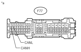
a.
U165197E01
0.454,1.11 0.679,2.015 0.679,2.015 0.851,2.015 false 1.017,1.786 0.888,1.786 0.888,1.786 0.551,1.11 false 1.04,1.709 1.462,1.846 0.422,0.137 10 CANL 0.879,1.941 1.302,2.078 0.422,0.137 10 CANH 0.054,0.044 0.477,0.182 0.422,0.137 10 *a 1.577,0.377 1.835,0.514 0.259,0.137 10 F77

Disconnect the cable from the negative (-) battery terminal before measuring the resistances of the CAN main wire and the CAN branch wire.

CAUTION:

For vehicles with an SRS system:

Wait at least 90 seconds after disconnecting the cable from the negative (-) battery terminal to disable the SRS system.


NOTICE:

When disconnecting the cable, some systems need to be initialized after the cable is reconnected (See page General>INTRODUCTION>REPAIR INSTRUCTION>INITIALIZATION).


b.

Measure the resistance according to the value(s) in the table below.

Standard Resistance:
Tester Connection Switch Condition Specified Condition
F77-1 (CANH) - F77-2 (CANL) Ignition switch off 54 to 69 Ω


Text in Illustration
*a Front view of wire harness connector
(to Multi-media Module Receiver Assembly)


OK

REPLACE MULTI-MEDIA MODULE RECEIVER ASSEMBLY

NG

REPAIR OR REPLACE CAN BRANCH WIRE OR CONNECTOR (MULTI-MEDIA MODULE RECEIVER ASSEMBLY)

3.CHECK FOR OPEN IN ONE SIDE OF CAN BRANCH WIRE (CENTER AIRBAG SENSOR ASSEMBLY)
NOTICE:

For vehicles without an airbag system, go to "Check for Open in One Side of CAN Branch Wire (Air Conditioning Amplifier Assembly)".


a.

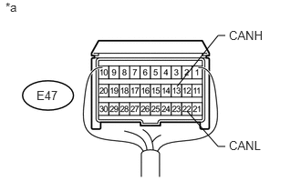
Disconnect the E47 center airbag sensor assembly connector.


b.

Select "Bus Check" on the intelligent tester (See page Power Source / Network>NETWORKING>CAN COMMUNICATION SYSTEM(for LHD)>DIAGNOSIS SYSTEM).

Result
Result Proceed to
"Airbag" is not displayed on the intelligent tester A
Several ECUs and sensors in addition to "Airbag" are displayed on the intelligent tester B


A

4.CHECK FOR OPEN IN ONE SIDE OF CAN BRANCH WIRE (CENTER AIRBAG SENSOR ASSEMBLY CAN BRANCH WIRE)

B

5.CHECK FOR OPEN IN ONE SIDE OF CAN BRANCH WIRE (AIR CONDITIONING AMPLIFIER ASSEMBLY)
4.CHECK FOR OPEN IN ONE SIDE OF CAN BRANCH WIRE (CENTER AIRBAG SENSOR ASSEMBLY CAN BRANCH WIRE)
a.
U165070E02
2.021,0.99 2.49,0.406 2.49,0.406 2.573,0.406 false 2.135,1.271 2.49,1.677 2.49,1.677 2.573,1.677 false 0.417,1.01 0.792,1.208 0.375,0.198 10 false E47 2.615,0.323 3.198,0.583 0.583,0.26 10 false CANH 0.063,0 0.271,0.177 0.208,0.177 10 false *a 2.615,1.583 3.115,1.802 0.5,0.219 10 false CANL

Disconnect the cable from the negative (-) battery terminal before measuring the resistances of the CAN main wire and the CAN branch wire.

CAUTION:

Wait at least 90 seconds after disconnecting the cable from the negative (-) battery terminal to disable the SRS system.


NOTICE:

When disconnecting the cable, some systems need to be initialized after the cable is reconnected (See page General>INTRODUCTION>REPAIR INSTRUCTION>INITIALIZATION).


b.

Measure the resistance according to the value(s) in the table below.

Standard Resistance:
Tester Connection Switch Condition Specified Condition
E47-13 (CANH) - E47-22 (CANL) Ignition switch off 54 to 69 Ω


Text in Illustration
*a Rear view of wire harness connector
(to Center Airbag Sensor Assembly)


OK

NG

REPAIR OR REPLACE CAN BRANCH WIRE OR CONNECTOR (CENTER AIRBAG SENSOR ASSEMBLY)

5.CHECK FOR OPEN IN ONE SIDE OF CAN BRANCH WIRE (AIR CONDITIONING AMPLIFIER ASSEMBLY)
a.

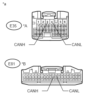
Disconnect the E35*1 or E81*2 air conditioning amplifier assembly connector.

*1: w/ Rear Air Conditioning System

*2: w/o Rear Air Conditioning System


b.

Select "Bus Check" on the intelligent tester (See page Power Source / Network>NETWORKING>CAN COMMUNICATION SYSTEM(for LHD)>DIAGNOSIS SYSTEM).

Result
Result Proceed to
"Air Conditioning Amplifier" is not displayed on the intelligent tester A
Several ECUs and sensors in addition to "Air Conditioning Amplifier" are displayed on the intelligent tester B


A

6.CHECK FOR OPEN IN ONE SIDE OF CAN BRANCH WIRE (AIR CONDITIONING AMPLIFIER ASSEMBLY CAN BRANCH WIRE)

B

7.CHECK FOR OPEN IN ONE SIDE OF CAN BRANCH WIRE (HEADLIGHT SWIVEL ECU ASSEMBLY)
6.CHECK FOR OPEN IN ONE SIDE OF CAN BRANCH WIRE (AIR CONDITIONING AMPLIFIER ASSEMBLY CAN BRANCH WIRE)
a.
U166125E01
0.089,0.048 0.328,0.296 0.239,0.248 10 *a 2.514,1.48 2.971,1.617 0.457,0.137 10 CANL 0.495,1.48 0.951,1.617 0.457,0.137 10 CANH 0.34,0.819 0.604,0.959 0.264,0.140 10 E35 0.81,0.819 1.049,1.067 0.239,0.248 10 *A 0.288,2.155 0.552,2.295 0.264,0.140 10 E81 0.758,2.155 0.997,2.404 0.239,0.248 10 *B 1.662,0.801 1.201,1.566 1.201,1.566 1.012,1.566 false 1.842,0.801 2.304,1.566 2.304,1.566 2.493,1.566 false 2.424,3.101 2.881,3.238 0.457,0.137 10 CANL 0.954,3.101 1.411,3.238 0.457,0.137 10 CANH 1.885,2.676 1.661,3.187 1.661,3.187 1.471,3.187 false 1.976,2.676 2.213,3.187 2.213,3.187 2.402,3.187 false

Disconnect the cable from the negative (-) battery terminal before measuring the resistances of the CAN main wire and the CAN branch wire.

CAUTION:

For vehicles with an SRS system:

Wait at least 90 seconds after disconnecting the cable from the negative (-) battery terminal to disable the SRS system.


NOTICE:

When disconnecting the cable, some systems need to be initialized after the cable is reconnected (See page General>INTRODUCTION>REPAIR INSTRUCTION>INITIALIZATION).


b.

Measure the resistance according to the value(s) in the table below.

Standard Resistance:
w/ Rear Air Conditioning System
Tester Connection Switch Condition Specified Condition
E35-3 (CANH) - E35-4 (CANL) Ignition switch off 54 to 69 Ω

w/o Rear Air Conditioning System
Tester Connection Switch Condition Specified Condition
E81-11 (CANH) - E81-12 (CANL) Ignition switch off 54 to 69 Ω


Text in Illustration
*A w/ Rear Air Conditioning System
*B w/o Rear Air Conditioning System
*a Front view of wire harness connector
(to Air Conditioning Amplifier Assembly)


OK

REPLACE AIR CONDITIONING AMPLIFIER ASSEMBLY

NG

REPAIR OR REPLACE CAN BRANCH WIRE OR CONNECTOR (AIR CONDITIONING AMPLIFIER ASSEMBLY)

7.CHECK FOR OPEN IN ONE SIDE OF CAN BRANCH WIRE (HEADLIGHT SWIVEL ECU ASSEMBLY)
NOTICE:

For vehicles without dynamic headlight auto leveling, go to "Check for Open in One Side of CAN Branch Wire (Main Body ECU)".


a.

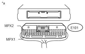
Disconnect the E101 headlight swivel ECU assembly connector.


b.

Select "Bus Check" on the intelligent tester (See page Power Source / Network>NETWORKING>CAN COMMUNICATION SYSTEM(for LHD)>DIAGNOSIS SYSTEM).

Result
Result Proceed to
"Headlight swivel (AFS)" is not displayed on the intelligent tester A
Several ECUs and sensors in addition to "Headlight swivel (AFS)" are displayed on the intelligent tester B


A

8.CHECK FOR OPEN IN ONE SIDE OF CAN BRANCH WIRE (HEADLIGHT SWIVEL ECU ASSEMBLY CAN BRANCH WIRE)

B

9.CHECK FOR OPEN IN ONE SIDE OF CAN BRANCH WIRE (MAIN BODY ECU)
8.CHECK FOR OPEN IN ONE SIDE OF CAN BRANCH WIRE (HEADLIGHT SWIVEL ECU ASSEMBLY CAN BRANCH WIRE)
a.
U165146E01
1.082,1.287 0.911,1.591 0.911,1.591 0.739,1.591 false 0.693,1.049 0.822,1.049 0.822,1.049 0.984,1.236 false 0.181,0.961 0.603,1.098 0.422,0.137 10 MPX2 0.247,1.509 0.669,1.647 0.422,0.137 10 MPX1 0.072,0.038 0.494,0.176 0.422,0.137 10 *a 2.855,1.042 3.200,1.180 0.346,0.137 10 E101

Disconnect the cable from the negative (-) battery terminal before measuring the resistances of the CAN main wire and the CAN branch wire.

CAUTION:

For vehicles with an SRS system:

Wait at least 90 seconds after disconnecting the cable from the negative (-) battery terminal to disable the SRS system.


NOTICE:

When disconnecting the cable, some systems need to be initialized after the cable is reconnected (See page General>INTRODUCTION>REPAIR INSTRUCTION>INITIALIZATION).


b.

Measure the resistance according to the value(s) in the table below.

Standard Resistance:
Tester Connection Switch Condition Specified Condition
E101-12 (MPX1) - E101-13 (MPX2) Ignition switch off 54 to 69 Ω


Text in Illustration
*a Rear view of wire harness connector
(to Headlight Swivel ECU Assembly)


OK

REPLACE HEADLIGHT SWIVEL ECU ASSEMBLY

NG

REPAIR OR REPLACE CAN BRANCH WIRE OR CONNECTOR (HEADLIGHT SWIVEL ECU ASSEMBLY)

9.CHECK FOR OPEN IN ONE SIDE OF CAN BRANCH WIRE (MAIN BODY ECU)
a.

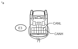
Disconnect the E3 main body ECU (cowl side junction block LH) connector.


b.

Select "Bus Check" on the intelligent tester (See page Power Source / Network>NETWORKING>CAN COMMUNICATION SYSTEM(for LHD)>DIAGNOSIS SYSTEM).

Result
Result Proceed to
"Main Body" is not displayed on the intelligent tester A
Several ECUs and sensors in addition to "Main Body" are displayed on the intelligent tester B


A

10.CHECK FOR OPEN IN ONE SIDE OF CAN BRANCH WIRE (MAIN BODY ECU CAN BRANCH WIRE)

B

11.SYSTEM CHECK
10.CHECK FOR OPEN IN ONE SIDE OF CAN BRANCH WIRE (MAIN BODY ECU CAN BRANCH WIRE)
a.
U166107E01
0.81,1.162 1.002,1.305 0.193,0.143 10 E3 0.052,0.044 0.222,0.205 0.170,0.161 10 *a 2.397,1.427 2.819,1.572 0.422,0.145 10 CANH 2.336,0.954 2.758,1.099 0.422,0.145 10 CANL 1.873,1.301 2.168,1.035 2.168,1.035 2.317,1.035 false 1.988,1.304 2.226,1.499 2.226,1.499 2.375,1.499 false

Disconnect the cable from the negative (-) battery terminal before measuring the resistances of the CAN main wire and the CAN branch wire.

CAUTION:

For vehicles with an SRS system:

Wait at least 90 seconds after disconnecting the cable from the negative (-) battery terminal to disable the SRS system.


NOTICE:

When disconnecting the cable, some systems need to be initialized after the cable is reconnected (See page General>INTRODUCTION>REPAIR INSTRUCTION>INITIALIZATION).


b.

Measure the resistance according to the value(s) in the table below.

Standard Resistance:
Tester Connection Switch Condition Specified Condition
E3-5 (CANH) - E3-6 (CANL) Ignition switch off 54 to 69 Ω


Text in Illustration
*a Rear view of wire harness connector
(to Main Body ECU [Cowl Side Junction Block LH])


OK

REPLACE MAIN BODY ECU (COWL SIDE JUNCTION BLOCK LH)

NG

REPAIR OR REPLACE CAN BRANCH WIRE OR CONNECTOR (MAIN BODY ECU)

11.SYSTEM CHECK
a.

Check the vehicle specifications.

Result
Result Proceed to
w/ Network Gateway ECU A
w/o Network Gateway ECU B


A

12.CHECK FOR OPEN IN ONE SIDE OF CAN BRANCH WIRE (NETWORK GATEWAY ECU CAN BRANCH WIRE)

B

13.CHECK FOR OPEN IN ONE SIDE OF CAN BRANCH WIRE (CLEARANCE WARNING ECU ASSEMBLY)
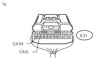
12.CHECK FOR OPEN IN ONE SIDE OF CAN BRANCH WIRE (NETWORK GATEWAY ECU CAN BRANCH WIRE)
a.
U165156E01
2.758,1.136 3.032,1.273 0.273,0.137 10 E31 1.244,1.295 1.046,1.491 1.046,1.491 0.922,1.491 false 1.109,1.777 1.255,1.777 1.255,1.777 1.352,1.293 false 0.433,1.416 0.822,1.554 0.389,0.137 10 CA1H 0.659,1.691 1.048,1.829 0.389,0.137 10 CA1L 0.07,0.056 0.371,0.193 0.301,0.137 10 *a

Disconnect the cable from the negative (-) battery terminal before measuring the resistances of the CAN main wire and the CAN branch wire.

CAUTION:

For vehicles with an SRS system:

Wait at least 90 seconds after disconnecting the cable from the negative (-) battery terminal to disable the SRS system.


NOTICE:

When disconnecting the cable, some systems need to be initialized after the cable is reconnected (See page General>INTRODUCTION>REPAIR INSTRUCTION>INITIALIZATION).


b.

Disconnect the E31 network gateway ECU connector.


c.

Measure the resistance according to the value(s) in the table below.

Standard Resistance:
Tester Connection Switch Condition Specified Condition
E31-16 (CA1H) - E31-15 (CA1L) Ignition switch off 54 to 69 Ω


Text in Illustration
*a Rear view of wire harness connector
(to Network Gateway ECU)


OK

NG

REPAIR OR REPLACE CAN BRANCH WIRE OR CONNECTOR (NETWORK GATEWAY ECU)

13.CHECK FOR OPEN IN ONE SIDE OF CAN BRANCH WIRE (CLEARANCE WARNING ECU ASSEMBLY)
NOTICE:

For vehicles without an TOYOTA parking assist-sensor system, go to "Check for Open in One Side of CAN Branch Wire (4WD Control ECU)".


a.

Disconnect the F12 clearance warning ECU assembly connector.


b.

Select "Bus Check" on the intelligent tester (See page Power Source / Network>NETWORKING>CAN COMMUNICATION SYSTEM(for LHD)>DIAGNOSIS SYSTEM).

Result
Result Proceed to
"Clearance Warning (Clearance Sonar)" is not displayed on the intelligent tester A
Several ECUs and sensors in addition to "Clearance Warning (Clearance Sonar)" are displayed on the intelligent tester B


A

14.CHECK FOR OPEN IN ONE SIDE OF CAN BRANCH WIRE (CLEARANCE WARNING ECU ASSEMBLY CAN BRANCH WIRE)

B

15.CHECK FOR OPEN IN ONE SIDE OF CAN BRANCH WIRE (4WD CONTROL ECU)
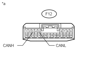
14.CHECK FOR OPEN IN ONE SIDE OF CAN BRANCH WIRE (CLEARANCE WARNING ECU ASSEMBLY CAN BRANCH WIRE)
a.
U166180E02
1.365,1.135 1.729,1.604 1.729,1.604 1.917,1.604 false 1.156,1.135 0.792,1.604 0.792,1.604 0.604,1.604 false 1.594,0.406 2.021,0.615 0.427,0.208 10 false F12 0.063,0.042 0.365,0.26 0.302,0.219 10 false *a 0.104,1.521 0.625,1.781 0.521,0.26 10 false CANH 1.958,1.521 2.448,1.708 0.49,0.188 10 false CANL

Disconnect the cable from the negative (-) battery terminal before measuring the resistances of the CAN main wire and the CAN branch wire.

CAUTION:

For vehicles with an SRS system:

Wait at least 90 seconds after disconnecting the cable from the negative (-) battery terminal to disable the SRS system.


NOTICE:

When disconnecting the cable, some systems need to be initialized after the cable is reconnected (See page General>INTRODUCTION>REPAIR INSTRUCTION>INITIALIZATION).


b.

Measure the resistance according to the value(s) in the table below.

Standard Resistance:
Tester Connection Switch Condition Specified Condition
F12-3 (CANH) - F12-5 (CANL) Ignition switch off 54 to 69 Ω


Text in Illustration
*a Front view of wire harness connector
(to Clearance Warning ECU Assembly)


OK

NG

REPAIR OR REPLACE CAN BRANCH WIRE OR CONNECTOR (CLEARANCE WARNING ECU ASSEMBLY)

15.CHECK FOR OPEN IN ONE SIDE OF CAN BRANCH WIRE (4WD CONTROL ECU)
a.

Disconnect the A27 4WD control ECU connector.


b.

Select "Bus Check" on the intelligent tester (See page Power Source / Network>NETWORKING>CAN COMMUNICATION SYSTEM(for LHD)>DIAGNOSIS SYSTEM).

Result
Result Proceed to
"Four Wheel Drive Control" is not displayed on the intelligent tester A
Several ECUs and sensors in addition to "Four Wheel Drive Control" are displayed on the intelligent tester B


A

16.CHECK FOR OPEN IN ONE SIDE OF CAN BRANCH WIRE (4WD CONTROL ECU CAN BRANCH WIRE)

B

17.CHECK FOR OPEN IN ONE SIDE OF BRANCH WIRE (SKID CONTROL ECU)
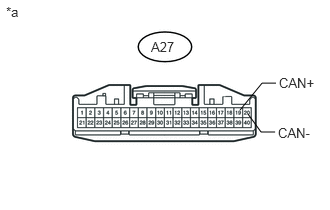
16.CHECK FOR OPEN IN ONE SIDE OF CAN BRANCH WIRE (4WD CONTROL ECU CAN BRANCH WIRE)
a.
U166183E02
2.5,1.146 2.729,0.865 2.729,0.865 2.875,0.865 false 2.583,1.188 2.719,1.375 2.719,1.375 2.865,1.375 false 1.573,0.406 1.969,0.604 0.396,0.198 10 false A27 0.063,0.042 0.354,0.271 0.292,0.229 10 false *a 2.906,0.781 3.396,0.958 0.49,0.177 10 false CAN+ 2.896,1.302 3.354,1.458 0.458,0.156 10 false CAN-

Disconnect the cable from the negative (-) battery terminal before measuring the resistances of the CAN main wire and the CAN branch wire.

CAUTION:

For vehicles with an SRS system:

Wait at least 90 seconds after disconnecting the cable from the negative (-) battery terminal to disable the SRS system.


NOTICE:

When disconnecting the cable, some systems need to be initialized after the cable is reconnected (See page General>INTRODUCTION>REPAIR INSTRUCTION>INITIALIZATION).


b.

Measure the resistance according to the value(s) in the table below.

Standard Resistance:
Tester Connection Switch Condition Specified Condition
A27-19 (CAN+) - A27-20 (CAN-) Ignition switch off 54 to 69 Ω


Text in Illustration
*a Front view of wire harness connector
(to 4WD Control ECU)


OK

NG

REPAIR OR REPLACE CAN BRANCH WIRE OR CONNECTOR (4WD CONTROL ECU)

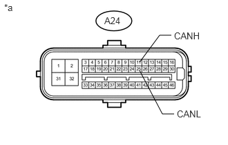
17.CHECK FOR OPEN IN ONE SIDE OF BRANCH WIRE (SKID CONTROL ECU)
a.
U166184E02
2.104,0.938 2.406,0.531 2.406,0.531 2.583,0.531 false 2.104,1.063 2.448,1.719 2.448,1.719 2.625,1.719 false 1.573,0.229 1.948,0.417 0.375,0.188 10 false A24 0.063,0.031 0.302,0.25 0.24,0.219 10 false *a 2.625,0.458 3.229,0.667 0.604,0.208 10 false CANH 2.667,1.635 3.198,1.885 0.531,0.25 10 false CANL

Disconnect the cable from the negative (-) battery terminal before measuring the resistances of the CAN main wire and the CAN branch wire.

CAUTION:

For vehicles with an SRS system:

Wait at least 90 seconds after disconnecting the cable from the negative (-) battery terminal to disable the SRS system.


NOTICE:

When disconnecting the cable, some systems need to be initialized after the cable is reconnected (See page General>INTRODUCTION>REPAIR INSTRUCTION>INITIALIZATION).


b.

Disconnect the A24 master cylinder solenoid (skid control ECU) connector.


c.

Measure the resistance according to the value(s) in the table below.

Standard Resistance:
Tester Connection Switch Condition Specified Condition
A24-11 (CANH) - A24-25 (CANL) Ignition switch off 54 to 69 Ω


Text in Illustration
*a Front view of wire harness connector
(to Master Cylinder Solenoid [Skid Control ECU])


OK

REPLACE MASTER CYLINDER SOLENOID (SKID CONTROL ECU)

NG

REPAIR OR REPLACE CAN BRANCH WIRE OR CONNECTOR (SKID CONTROL ECU)