BRAKE SYSTEM (OTHER) BRAKE BOOSTER(for LHD) REMOVAL
CAUTION / NOTICE / HINT
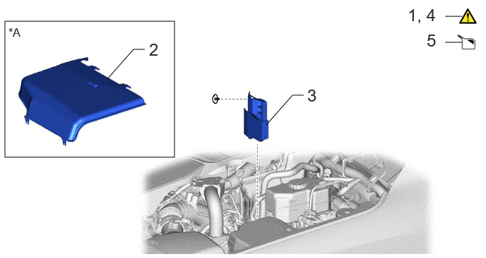
| Procedure | Part Name Code |

|

|

|
|
|---|---|---|---|---|---|
| 1 | PRECAUTION | - | ( ) |
- | - |
| 2 | ENGINE SIDE COVER LH | 51474B | - | - | - |
| 3 | UPPER ENGINE SIDE UNDER COVER PLATE LH | 51478C | - | - | - |
| 4 | ACCUMULATOR PRESSURE ZERO DOWN | - | () |
- | - |
| 5 | DRAIN BRAKE FLUID | - | - | () |
- |
| *A | except 1GR-FE | - | - |

| Procedure | Part Name Code |
|
|
|
|
|---|---|---|---|---|---|
| 6 | LOWER NO. 1 INSTRUMENT PANEL AIRBAG ASSEMBLY | 73900 | - | - | - |
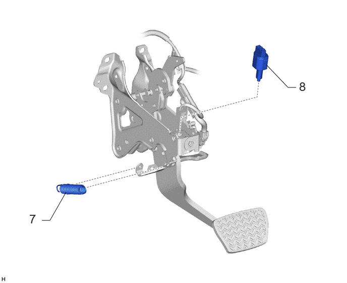
| Procedure | Part Name Code |
|
|
|
|
|---|---|---|---|---|---|
| 7 | BRAKE PEDAL RETURN SPRING | 47101A | - | - | - |
| 8 | STOP LIGHT SWITCH ASSEMBLY | 84340 | - | - | - |
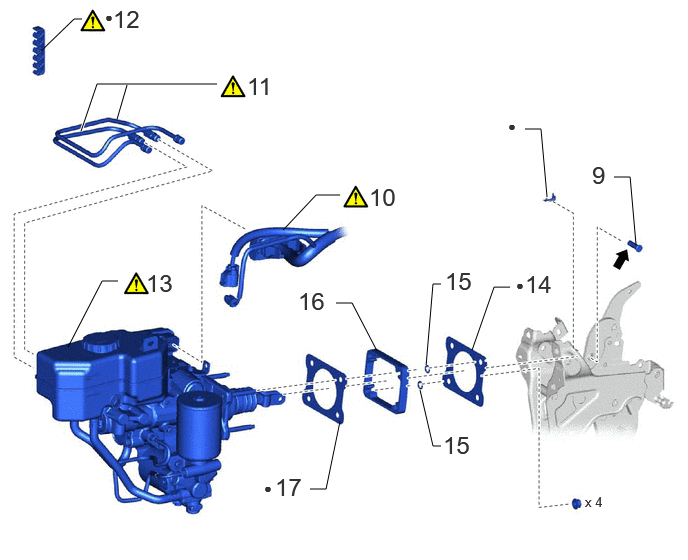
| Procedure | Part Name Code |
|
|
|
|
|---|---|---|---|---|---|
| 9 | PUSH ROD PIN | 47264A | - | - | - |
| 10 | ENGINE ROOM MAIN WIRE | 82111 | () |
- | - |
| 11 | BRAKE TUBE | - | () |
- | - |
| 12 | NO. 2 BRAKE TUBE CLAMP | 47372 | () |
- | - |
| 13 | BRAKE BOOSTER WITH MASTER CYLINDER ASSEMBLY | 47210L | () |
- | - |
| 14 | BRAKE MASTER CYLINDER GASKET | 44785D | - | - | - |
| 15 | BOOSTER BRACKET STOPPER RING | - | - | - | - |
| 16 | BRAKE BOOSTER BRACKET | - | - | - | - |
| 17 | BRAKE MASTER CYLINDER GASKET | 44785D | - | - | - |
| ● | Non-reusable part | - | - |

|
Lithium soap base glycol grease | - | - |
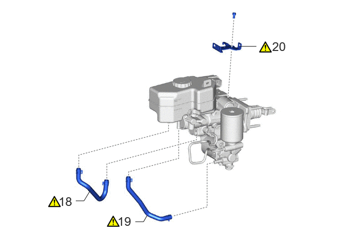
| Procedure | Part Name Code |
|
|
|
|
|---|---|---|---|---|---|
| 18 | NO. 1 RESERVOIR HOSE | - | () |
- | - |
| 19 | NO. 2 RESERVOIR HOSE | - | () |
- | - |
| 20 | NO. 1 WIRE CLAMP BRACKET | - | () |
- | - |
CAUTION / NOTICE / HINT
The necessary procedures (adjustment, calibration, initialization, or registration) that must be performed after parts are removed and installed, or replaced during brake booster with master cylinder assembly removal/installation are shown below.
| Replaced Part or Performed Procedures | Necessary procedures | Effect/Inoperative Function when Necessary Procedures are not Performed | Link |
|---|---|---|---|
| No. 1 Skid control ECU (brake booster with master cylinder assembly) | Update ECU security key | Vehicle control history (RoB) are stored | () |
|
1.
Bleed air
2.
Perform "Calibration" |
·
DTCs are stored
·
ABS warning light illuminates
·
Brake system warning light (yellow indicator) illuminates
·
Slip indicator light illuminates
·
Electronically controlled brake system disabled or malfunctions |
() |
|
| Disconnect cable from negative (-) battery terminal | Memorize steering angle neutral point | Parking assist monitor system | () |
| Multi-terrain monitor system | () |
||
| Panoramic view monitor system | () |
- HINT:
-
·
When the cable is disconnected/reconnected to the battery terminal, systems temporarily stop operating. However, each system has a function that completes learning the first time the system is used.
-Learning completes when vehicle is driven
Effect/Inoperative Function When Necessary Procedures are not Performed Necessary Procedures Link Stop and start system Drive the vehicle until stop and start control is permitted (approximately 5 to 60 minutes) ( )Lighting system (EXT) Cornering lights Drive the vehicle straight ahead at 35 km/h (22 mph) or more for 5 seconds or more. ( )Pre-collision system Lane tracing assist system Lane departure alert system Adaptive high beam system
-Learning completes when vehicle is operated normally
Effect/Inoperative Function When Necessary Procedures are not Performed Necessary Procedures Link Power back door system Fully close the back door by hand.
- HINT:
-
Initialization is not necessary if the above procedures are performed while the back door is closed.
( )Air conditioning system After the ignition switch is turned to ON, the servo motor and expansion valve standard position is recognized. -
CAUTION / NOTICE / HINT
- NOTICE:
-
·
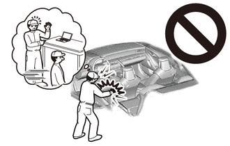
While the battery is connected, even if the ignition switch is off, the brake control system activates when the brake pedal is depressed or any door courtesy switch turns on. Therefore, when servicing the brake system components, do not operate the brake pedal or open/close the doors while the battery is connected.
·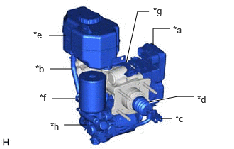 2.25,0.667 2.25,0.417 2.25,0.417 2.5,0.417 false 2.354,1.74 2.521,1.74 false 2.188,1.5 2.604,1.417 2.604,1.417 2.854,1.417 true 0.719,0.521 0.969,0.521 false 0.771,1.448 1.104,1.448 false 0.729,1.01 1.063,1.01 false 1.854,0.917 2.021,0.167 2.021,0.167 2.188,0.167 true 0.938,1.833 1.271,1.833 false 2.542,0.354 2.792,0.521 0.25,0.167 10 false *a 0.521,0.927 0.771,1.094 0.25,0.167 10 false *b 2.573,1.656 2.823,1.906 0.25,0.25 10 false *c 2.896,1.375 3.229,1.708 0.333,0.333 10 false *d 0.49,0.427 0.74,0.677 0.25,0.25 10 false *e 0.583,1.354 0.917,1.604 0.333,0.25 10 false *f 2.25,0.073 2.5,0.323 0.25,0.25 10 false *g 0.74,1.771 1.073,2.021 0.333,0.25 10 false *h
*a No. 1 Skid Control ECU *b No. 1 Reservoir Hose and No. 2 Reservoir Hose *c Master Cylinder Push Rod Clevis *d Boot *e Brake Master Cylinder Reservoir *f No. 1 Brake Actuator Tube *g No. 1 Wire Clamp Bracket *h Brake Booster with Accumulator Pump Assembly
Do not carry the brake booster with master cylinder assembly by the parts shown in the illustration.
PROCEDURE

 1. PRECAUTION
|
|
|
51474B 2.REMOVE ENGINE SIDE COVER LH (except 1GR-FE)
51478C 3.REMOVE UPPER ENGINE SIDE UNDER COVER PLATE LH
4.PERFORM ACCUMULATOR PRESSURE ZERO DOWN
|
|
Click here() |
5.DRAIN BRAKE FLUID
|
|
|
73900 6.REMOVE LOWER NO. 1 INSTRUMENT PANEL AIRBAG ASSEMBLY
47101A 7.REMOVE BRAKE PEDAL RETURN SPRING

84340 8.REMOVE STOP LIGHT SWITCH ASSEMBLY
47264A 9.REMOVE PUSH ROD PIN

82111 10.DISCONNECT ENGINE ROOM MAIN WIRE


|
Release the lock lever |

|
Disconnect the connector |
Disconnect the brake fluid level warning switch connector.
- NOTICE:
-
Be careful not to allow any brake fluid to enter the connector.
Disengage the clamp to disconnect the front engine room main wire from the brake booster with master cylinder assembly.
Release the lock lever and disconnect the connector from the brake booster with master cylinder assembly.
- NOTICE:
-
Be careful not to allow any brake fluid to enter the connector.
11.REMOVE BRAKE TUBE
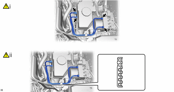
Using a union nut wrench, remove the 2 tubes from the brake actuator assembly and brake booster with master cylinder assembly.
- NOTICE:
-
·
Do not kink or damage the brake tubes.
·Do not allow any foreign matter such as dirt or dust to enter the brake tubes from the connecting parts.
Disengage the 2 clamps and remove the 2 brake tubes from the No. 2 brake tube clamp.
- NOTICE:
-
Do not kink or damage the brake tubes.
47372 12.REMOVE NO. 2 BRAKE TUBE CLAMP
|
|
() |
47210L 13.REMOVE BRAKE BOOSTER WITH MASTER CYLINDER ASSEMBLY
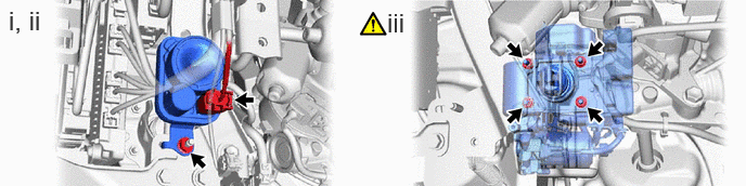
Disconnect the connector.
Remove the nut and siren.
Remove the 4 nuts and brake booster with master cylinder assembly.
- NOTICE:
-
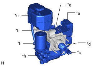 2.25,0.667 2.25,0.417 2.25,0.417 2.5,0.417 false 2.354,1.74 2.521,1.74 false 2.188,1.5 2.604,1.417 2.604,1.417 2.854,1.417 true 0.719,0.521 0.969,0.521 false 0.771,1.448 1.104,1.448 false 0.729,1.01 1.063,1.01 false 1.854,0.917 2.021,0.167 2.021,0.167 2.188,0.167 true 0.938,1.833 1.271,1.833 false 2.542,0.354 2.792,0.521 0.25,0.167 10 false *a 0.521,0.927 0.771,1.094 0.25,0.167 10 false *b 2.573,1.656 2.823,1.906 0.25,0.25 10 false *c 2.896,1.375 3.229,1.708 0.333,0.333 10 false *d 0.49,0.427 0.74,0.677 0.25,0.25 10 false *e 0.583,1.354 0.917,1.604 0.333,0.25 10 false *f 2.25,0.073 2.5,0.323 0.25,0.25 10 false *g 0.74,1.771 1.073,2.021 0.333,0.25 10 false *h
*a No. 1 Skid Control ECU *b No. 1 Reservoir Hose and No. 2 Reservoir Hose *c Master Cylinder Push Rod Clevis *d Boot *e Brake Master Cylinder Reservoir *f No. 1 Brake Actuator Tube *g No. 1 Wire Clamp Bracket *h Brake Booster with Accumulator Pump Assembly
-
·
Do not apply excessive force to the brake lines.
·Be careful not to allow any brake fluid to enter the connector.
·Do not carry the brake booster with master cylinder assembly by the parts shown in the illustration.
44785D 14.REMOVE BRAKE MASTER CYLINDER GASKET

15.REMOVE BOOSTER BRACKET STOPPER RING

16.REMOVE BRAKE BOOSTER BRACKET

44785D 17.REMOVE BRAKE MASTER CYLINDER GASKET

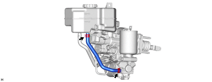
18.REMOVE NO. 1 RESERVOIR HOSE
|
|
|
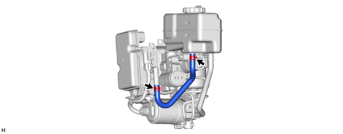
19.REMOVE NO. 2 RESERVOIR HOSE
|
|
|
20.REMOVE NO. 1 WIRE CLAMP BRACKET
|
|
|
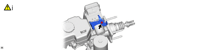
Using a 5 mm long hexagon socket wrench, remove the bolt and No. 1 wire clamp bracket.