SEAT FRONT POWER SEAT CONTROL SYSTEM(w/ Memory) Power Seat Power Easy Access System Function does not Operate
DESCRIPTION
Perform either of the following and check that the driver seat moves rearward:
With the ignition switch off and the shift lever in P, unfasten the driver seat seat belt.
With the shift lever in P and the driver seat seat belt unfastened, turn the ignition switch off.
Perform either of the following and check that the driver seat moves forward:
With the shift lever in P, fasten the driver seat seat belt.
With the shift lever in P, turn the ignition switch from off to ON.
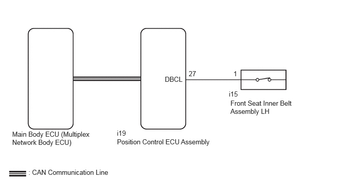
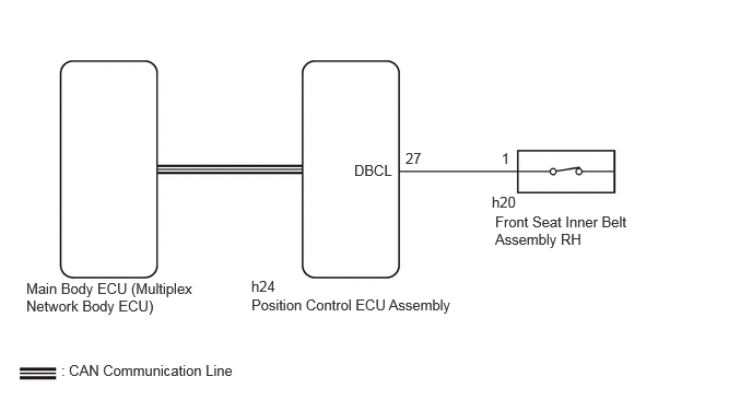
WIRING DIAGRAM
for LHD:
for RHD:
CAUTION / NOTICE / HINT
- NOTICE:
-
·
The front power seat control system uses the CAN communication system. First, confirm that there is no malfunction in the CAN communication system. Refer to the How to Proceed with Troubleshooting procedure.
·Before replacing the main body ECU (multiplex network body ECU), refer to Service Bulletin.
- HINT:
-
When troubleshooting a function, first make sure that the function is set to the default setting.
-
Click hereVehicle Interior>SEAT>FRONT POWER SEAT CONTROL SYSTEM (w/ Memory)>CUSTOMIZE PARAMETERS
PROCEDURE
Check the vehicle type.
- Result:
-
Result Proceed to for LHD A for RHD B
A
B
Check that each function of the power seat operates normally by using the front power seat switch LH.
Click hereVehicle Interior>SEAT>FRONT POWER SEAT CONTROL SYSTEM (w/ Memory)>OPERATION CHECK
- Result:
-
Result Proceed to Power seat functions operate normally A All power seat functions do not operate B One or more power seat motors do not operate C
A
B
C
Click hereVehicle Interior>SEAT BELT>FRONT SEAT INNER BELT ASSEMBLY (for Power Seat)>INSPECTION
- Result:
-
Proceed to OK NG
OK
NG
Disconnect the i19 position control ECU assembly connector.
Disconnect the i15 front seat inner belt assembly LH connector.
Measure the resistance according to the value(s) in the table below.
- Standard Resistance:
-
Tester Connection Condition Specified Condition Click Location & Routing(i19,i15)Location & Routingewd_type=routing;type=c,c;code=i19,i15
Click Connector(i19)Seat>Front Seat Wire LH>Front Position Control ECU Assembly LHewd_type=component;type=c;code=i19;pinno=27
Click Connector(i15)Seat>Front Seat Wire LH>Front Seat Belt Set LHewd_type=component;type=c;code=i15;pinno=1
i19-27 (DBCL) - i15-1 Always Below 1 Ω i19-27 (DBCL) or i15-1 - Body ground Always 10 kΩ or higher
- Result:
-
Proceed to OK NG
OK
NG
Check that each function of the power seat operates normally by using the front power seat switch RH.
Click hereVehicle Interior>SEAT>FRONT POWER SEAT CONTROL SYSTEM (w/ Memory)>OPERATION CHECK
- Result:
-
Result Proceed to Power seat functions operate normally A All power seat functions do not operate B One or more power seat motors do not operate C
A
B
C
Click hereVehicle Interior>SEAT BELT>FRONT SEAT INNER BELT ASSEMBLY (for Power Seat)>INSPECTION
- Result:
-
Proceed to OK NG
OK
NG
Disconnect the h24 position control ECU assembly connector.
Disconnect the h20 front seat inner belt assembly RH connector.
Measure the resistance according to the value(s) in the table below.
- Standard Resistance:
-
Tester Connection Condition Specified Condition Click Location & Routing(h24,h20)Location & Routingewd_type=routing;type=c,c;code=h24,h20
Click Connector(h24)Seat>Front Seat Wire RH>Front Position Control ECU Assembly RHewd_type=component;type=c;code=h24;pinno=27
Click Connector(h20)Seat>Front Seat Wire RH>Front Seat Belt Set RHewd_type=component;type=c;code=h20;pinno=1
h24-27 (DBCL) - h20-1 Always Below 1 Ω h24-27 (DBCL) or h20-1 - Body ground Always 10 kΩ or higher
- Result:
-
Proceed to OK NG
OK
NG