STEERING COLUMN STEERING COLUMN ASSEMBLY(for Power Tilt and Power Telescopic Steering Column) INSTALLATION
CAUTION / NOTICE / HINT
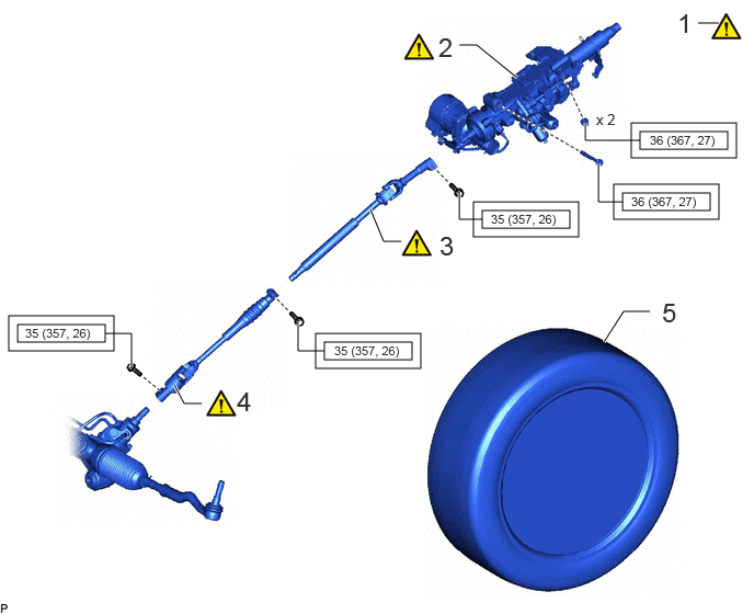
| Procedure | Part Name Code |

|

|

|
|
|---|---|---|---|---|---|
| 1 | ALIGN FRONT WHEELS FACING STRAIGHT AHEAD | - | - | - | - |
| 2 | ELECTRIC POWER STEERING COLUMN SUB-ASSEMBLY | 4520A | ( ) |
- | - |
| 3 | STEERING INTERMEDIATE SHAFT ASSEMBLY | 45220 | () |
- | - |
| 4 | NO. 2 STEERING INTERMEDIATE SHAFT SUB-ASSEMBLY | 45203 | () |
- | - |
| 5 | FRONT WHEEL LH | - | - | - | - |

|
Tightening torque for "Major areas involving basic vehicle performance such as moving/turning/stopping": N*m (kgf*cm, ft.*lbf) | - | - |
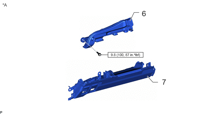
| Procedure | Part Name Code |
|
|
|
|
|---|---|---|---|---|---|
| 6 | AIR DUCT SUB-ASSEMBLY | - | - | - | - |
| 7 | LOWER NO. 1 INSTRUMENT PANEL AIRBAG ASSEMBLY | 73900 | - | - | - |
| *A | for LHD | - | - |

|
N*m (kgf*cm, ft.*lbf): Specified torque | - | - |
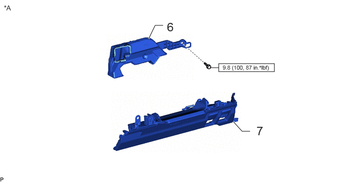
| Procedure | Part Name Code |
|
|
|
|
|---|---|---|---|---|---|
| 6 | AIR DUCT SUB-ASSEMBLY | - | - | - | - |
| 7 | LOWER NO. 1 INSTRUMENT PANEL AIRBAG ASSEMBLY | 73900 | - | - | - |
| *A | for RHD | - | - |
|
|
N*m (kgf*cm, ft.*lbf): Specified torque | - | - |
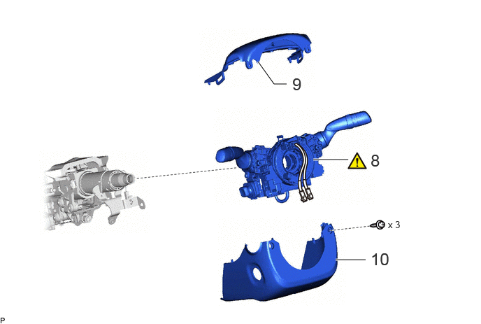
| Procedure | Part Name Code |
|
|
|
|
|---|---|---|---|---|---|
| 8 | TURN SIGNAL SWITCH ASSEMBLY WITH SPIRAL CABLE SUB-ASSEMBLY | - | () |
- | - |
| 9 | UPPER STEERING COLUMN COVER | 45286B | - | - | - |
| 10 | LOWER STEERING COLUMN COVER SUB-ASSEMBLY | 45024 | - | - | - |
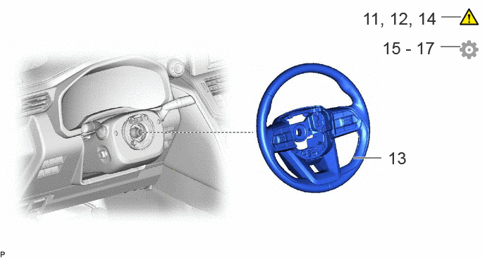
| Procedure | Part Name Code |
|
|
|
|
|---|---|---|---|---|---|
| 11 | ALIGN FRONT WHEELS FACING STRAIGHT AHEAD | - | - | - | - |
| 12 | ADJUST SPIRAL CABLE SUB-ASSEMBLY | - | () |
- | - |
| 13 | STEERING WHEEL ASSEMBLY | 45100 | - | - | - |
| 14 | CUSTOMIZE POWER TILT AND POWER TELESCOPIC STEERING COLUMN SYSTEM | - | () |
- | - |
| 15 | UPDATE ECU SECURITY KEY | - | - | - | () |
| 16 | INITIALIZATION AFTER RECONNECTING AUXILIARY BATTERY TERMINAL | - | - | - | () |
| 17 | PERFORM INITIALIZATION | - | - | - | () |
CAUTION / NOTICE / HINT
- HINT:
-
·
Use the same procedure for RHD and LHD vehicles.
·The procedure listed below is for LHD vehicles.
PROCEDURE

 1.ALIGN FRONT WHEELS FACING STRAIGHT AHEAD
4520A 2.INSTALL ELECTRIC POWER STEERING COLUMN SUB-ASSEMBLY
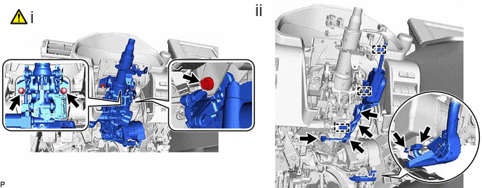
Install the electric power steering column sub-assembly with the 2 nuts and bolt.
- Torque:
- 36 N*m (367 kgf*cm, 27 ft.*lbf)
- NOTICE:
-
Temporarily tighten the bolt, and then fully tighten the bolt and 2 nuts in the order of 2 nuts and bolt.
Connect each connector and engage each wire harness clamp to the electric power steering column sub-assembly.
45220 3.INSTALL STEERING INTERMEDIATE SHAFT ASSEMBLY
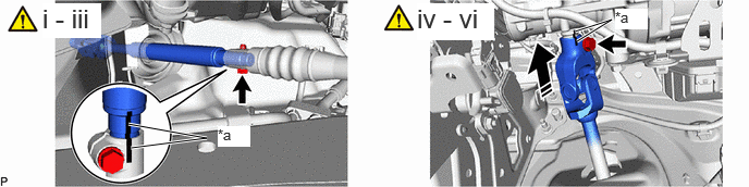
| *a | Matchmark | - | - |

|
Slide in this Direction | - | - |
Align the matchmarks on the steering intermediate shaft assembly and No. 2 steering intermediate shaft assembly.
- HINT:
-
Perform this procedure only when replacement of the steering intermediate shaft assembly and No. 2 steering intermediate shaft assembly is necessary.
Install the steering intermediate shaft assembly and No. 2 steering intermediate shaft assembly.
- HINT:
-
Perform this procedure only when replacement of the steering intermediate shaft assembly and No. 2 steering intermediate shaft assembly is necessary.
Install the bolt.
- Torque:
- 35 N*m (357 kgf*cm, 26 ft.*lbf)
- HINT:
-
Perform this procedure only when replacement of the steering intermediate shaft assembly and No. 2 steering intermediate shaft assembly is necessary.
Align the matchmarks on the steering intermediate shaft assembly and electric power steering column sub-assembly.
Install the steering intermediate shaft assembly to the electric power steering column sub-assembly.
Install the bolt.
- Torque:
- 35 N*m (357 kgf*cm, 26 ft.*lbf)
45203 4.CONNECT NO. 2 STEERING INTERMEDIATE SHAFT SUB-ASSEMBLY
|
|
Click here() |
5.INSTALL FRONT WHEEL LH
6.INSTALL AIR DUCT SUB-ASSEMBLY
- Torque:
- 9.8 N*m (100 kgf*cm, 87 in.*lbf)
73900 7.INSTALL LOWER NO. 1 INSTRUMENT PANEL AIRBAG ASSEMBLY
8.INSTALL TURN SIGNAL SWITCH ASSEMBLY WITH SPIRAL CABLE SUB-ASSEMBLY
|
|
|
45286B 9.INSTALL UPPER STEERING COLUMN COVER
45024 10.INSTALL LOWER STEERING COLUMN COVER SUB-ASSEMBLY
11.ALIGN FRONT WHEELS FACING STRAIGHT AHEAD
12.ADJUST SPIRAL CABLE SUB-ASSEMBLY
|
|
Click here() |
45100 13.INSTALL STEERING WHEEL ASSEMBLY
14. CUSTOMIZE POWER TILT AND POWER TELESCOPIC STEERING COLUMN SYSTEM
|
|
|
Perform the customization settings.
Click hereSteering>STEERING COLUMN>POWER TILT AND POWER TELESCOPIC STEERING COLUMN SYSTEM>CUSTOMIZE PARAMETERS
15. UPDATE ECU SECURITY KEY
16. INITIALIZATION AFTER RECONNECTING AUXILIARY BATTERY TERMINAL
Click hereGeneral>SETUP>WHEN DISCONNECTING OR RECONNECTING BATTERY TERMINAL>WORK PROCEDURE
- HINT:
-
When disconnecting and reconnecting the battery, there is an automatic learning function that completes learning when the respective system is used.
-
Click hereGeneral>SETUP>WHEN DISCONNECTING OR RECONNECTING BATTERY TERMINAL>AUTOMATIC LEARNING CHART
17.PERFORM INITIALIZATION