V35A-FTS FUEL FUEL PRESSURE SENSOR(for High Pressure) INSTALLATION
CAUTION / NOTICE / HINT
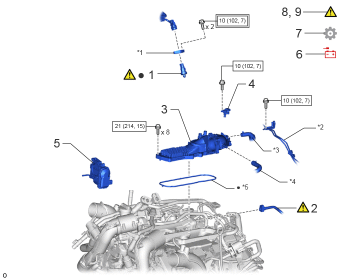
| Procedure | Part Name Code |

|

|

|
|
|---|---|---|---|---|---|
| 1 | FUEL PRESSURE SENSOR | 89458 | ( ) |
- | - |
| 2 | FUEL TUBE SUB-ASSEMBLY | 23910A | () |
- | - |
| 3 | INTAKE AIR SURGE TANK ASSEMBLY | 17190 | - | - | - |
| 4 | NO. 3 TURBO PRESSURE SENSOR | 89421Q | - | - | - |
| 5 | THROTTLE WITH THROTTLE POSITION SENSOR BODY ASSEMBLY | 22030 | - | - | - |
| 6 | CONNECT CABLE TO NEGATIVE BATTERY TERMINAL | - | - | - | - |
| 7 | INITIALIZATION AFTER RECONNECTING BATTERY TERMINAL | - | - | - | () |
| 8 | INSPECT FOR FUEL LEAK | - | () |
- | - |
| 9 | PERFORM INITIALIZATION | - | () |
- | - |
| *1 | NO. 1 FUEL PRESSURE SENSOR HOLDER | *2 | NO. 3 TURBO WATER PIPE SUB-ASSEMBLY |
| *3 | VENTILATION HOSE | *4 | NO. 3 VAPOR FEED HOSE |
| *5 | GASKET | - | - |

|
Tightening torque for "Major areas involving basic vehicle performance such as moving/turning/stopping": N*m (kgf*cm, ft.*lbf) |

|
N*m (kgf*cm, ft.*lbf): Specified torque |
| ● | Non-reusable part | - | - |
CAUTION / NOTICE / HINT
- NOTICE:
-
This procedure includes the installation of small-head bolts. Refer to Small-Head Bolts of Basic Repair Hint to identify the small-head bolts.
-
Click hereGeneral>INTRODUCTION>REPAIR INSTRUCTION>PRECAUTION
- HINT:
-
Perform "Inspection After Repair" after replacing the fuel pressure sensor.
-
Click hereEngine / Hybrid System>V35A-FTS (ENGINE CONTROL)>SFI SYSTEM>INITIALIZATION
PROCEDURE

 89458 1.INSTALL FUEL PRESSURE SENSOR
|
|
|
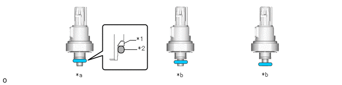
| *1 | No. 1 Back-up Ring | *2 | O-Ring |
| *a | Correct | *b | Incorrect |
Check the O-ring position of the new fuel pressure sensor.
- NOTICE:
-
If the O-ring is not in the correct position, set it in the correct position.
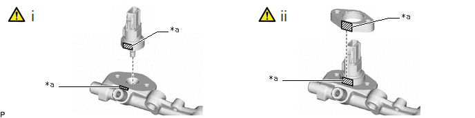
| *a | Flat Surface | - | - |
Set the fuel pressure sensor to the No. 2 fuel delivery pipe sub-assembly RH.
- NOTICE:
-
·
Align the flat surface on the fuel pressure sensor with the flat surface on the No. 2 fuel delivery pipe sub-assembly RH.
·Do not allow dust or dirt to enter the sensor.
·Do not tilt the fuel pressure sensor when inserting it into the No. 2 fuel delivery pipe sub-assembly RH.
·To prevent the O-ring and No. 1 backup ring from coming off the fuel pressure sensor, do not pull out the fuel pressure sensor after inserting the fuel pressure sensor.
·If a fuel pressure sensor is dropped or struck, replace it with a new one.
Set the No. 1 fuel pressure sensor holder to the No. 2 fuel delivery pipe sub-assembly RH.
- NOTICE:
-
·
Align the flat surface on the No. 1 fuel pressure sensor holder with the flat surface on the fuel pressure sensor.
·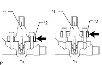 0.75,1 0.417,0.385 0.417,0.385 0.281,0.385 true 1.167,1.25 1.333,0.75 1.333,0.75 1.448,0.75 true 2.5,1.01 2.094,0.375 2.094,0.375 1.958,0.375 true 2.938,1.115 3.021,0.698 3.021,0.698 3.135,0.698 true 0.104,0.323 0.344,0.479 0.24,0.156 10 false *1 1.479,0.688 1.677,0.844 0.198,0.156 10 false *2 0.677,1.99 0.875,2.135 0.198,0.146 10 false *a 2.458,1.99 2.656,2.146 0.198,0.156 10 false *b 1.74,0.313 1.979,0.469 0.24,0.156 10 false *1 3.177,0.635 3.375,0.792 0.198,0.156 10 false *2
*1 Fuel Pressure Sensor *2 No. 1 Fuel Pressure Sensor Holder *a CORRECT *b INCORRECT
Make sure to install the No. 1 fuel pressure sensor holder in the correct direction.
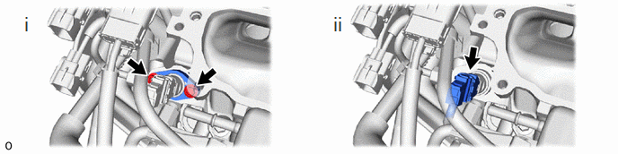
Install the 2 bolts.
- Torque:
- 10 N*m (102 kgf*cm, 7 ft.*lbf)
Connect the connector to the fuel pressure sensor.
23910A 2.CONNECT FUEL TUBE SUB-ASSEMBLY
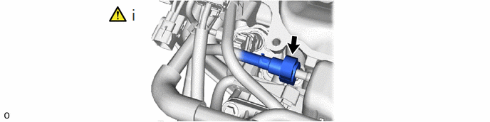
Connect the fuel tube sub-assembly to the No. 1 fuel delivery pipe sub-assembly RH.
Click hereEngine / Hybrid System>V35A-FTS (FUEL)>FUEL SYSTEM>PRECAUTION
17190 3.INSTALL INTAKE AIR SURGE TANK ASSEMBLY
89421Q 4.INSTALL NO. 3 TURBO PRESSURE SENSOR
22030 5.INSTALL THROTTLE WITH THROTTLE POSITION SENSOR BODY ASSEMBLY
6.CONNECT CABLE TO NEGATIVE BATTERY TERMINAL
7. INITIALIZATION AFTER RECONNECTING BATTERY TERMINAL
Click hereGeneral>SETUP>WHEN DISCONNECTING OR RECONNECTING BATTERY TERMINAL>WORK PROCEDURE
- HINT:
-
When disconnecting and reconnecting the battery, there is an automatic learning function that completes learning when the respective system is used.
-
Click hereGeneral>SETUP>WHEN DISCONNECTING OR RECONNECTING BATTERY TERMINAL>AUTOMATIC LEARNING CHART
8.INSPECT FOR FUEL LEAK
9.PERFORM INITIALIZATION
Perform "Inspection After Repair" after replacing the fuel pressure sensor.
Click hereEngine / Hybrid System>V35A-FTS (ENGINE CONTROL)>SFI SYSTEM>INITIALIZATION