1GR-FE FUEL FUEL INJECTOR INSTALLATION
CAUTION / NOTICE / HINT
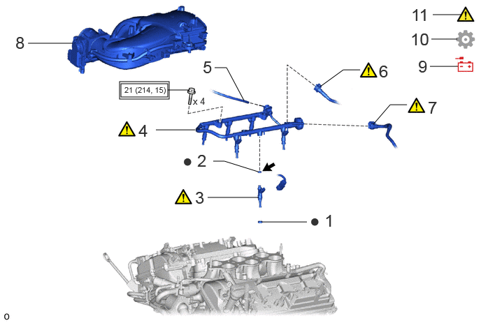
| Procedure | Part Name Code |

|

|

|
|
|---|---|---|---|---|---|
| 1 | INJECTOR VIBRATION INSULATOR | 23291 | - | - | - |
| 2 | FUEL INJECTOR O-RING | 23250B | - | - | - |
| 3 | FUEL INJECTOR ASSEMBLY | 23250 | ( ) |
- | - |
| 4 | FUEL DELIVERY PIPE SUB-ASSEMBLY | 23807 | () |
- | - |
| 5 | VACUUM TRANSMITTING HOSE ASSEMBLY | 25760 | - | - | - |
| 6 | NO. 2 FUEL PIPE SUB-ASSEMBLY | 23802B | () |
- | - |
| 7 | NO. 1 FUEL PIPE SUB-ASSEMBLY | 23801P | () |
- | - |
| 8 | INTAKE AIR SURGE TANK | 17129 | - | - | - |
| 9 | CONNECT CABLE TO NEGATIVE BATTERY TERMINAL | - | - | - | - |
| 10 | INITIALIZATION AFTER RECONNECTING BATTERY TERMINAL | - | - | - | () |
| 11 | INSPECT FOR FUEL LEAK | - | () |
- | - |

|
Tightening torque for "Major areas involving basic vehicle performance such as moving/turning/stopping": N*m (kgf*cm, ft.*lbf) | ● | Non-reusable part |

|
Spindle oil or gasoline | - | - |
PROCEDURE

 23291 1.INSTALL INJECTOR VIBRATION INSULATOR
23250B 2.INSTALL FUEL INJECTOR O-RING
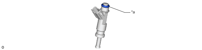
| *a | Apply spindle oil or gasoline | - | - |
23250 3.INSTALL FUEL INJECTOR ASSEMBLY
|
|
|
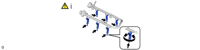
Install the 6 fuel injector assemblies.
While turning each fuel injector assembly left and right, install it to the fuel delivery pipe sub-assembly.
Position the fuel injector assembly connectors so they are facing outward.
23807 4.INSTALL FUEL DELIVERY PIPE SUB-ASSEMBLY
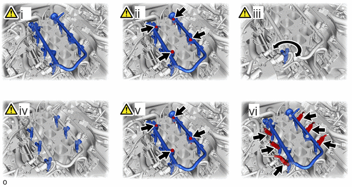
Place the fuel delivery pipe sub-assembly together with the 6 fuel injector assemblies on the intake manifold.
Temporarily install the 4 bolts, which are used to hold the fuel delivery pipe sub-assembly to the intake manifold.
Check that the fuel injector assemblies rotate smoothly.
If any fuel injector assembly does not rotate smoothly, replace the O-ring of that fuel injector assembly.
Position the fuel injector assemblies so that the connectors are facing outward.
Tighten the 4 bolts, which are used to hold the fuel delivery pipe sub-assembly to the intake manifold.
- Torque:
- 21 N*m (214 kgf*cm, 15 ft.*lbf)
Connect the 6 connectors to the 6 fuel injector assemblies.
25760 5.CONNECT VACUUM TRANSMITTING HOSE ASSEMBLY
23802B 6.CONNECT NO. 2 FUEL PIPE SUB-ASSEMBLY
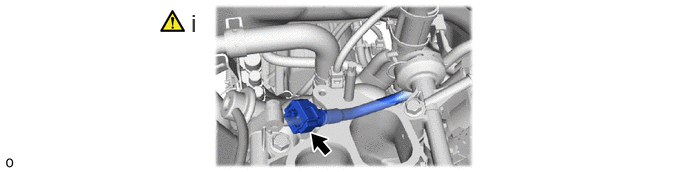
Connect the No. 2 fuel pipe sub-assembly to the fuel pressure regulator assembly.
Click hereEngine / Hybrid System>1GR-FE (FUEL)>FUEL SYSTEM>PRECAUTION
23801P 7.CONNECT NO. 1 FUEL PIPE SUB-ASSEMBLY
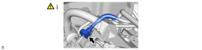
Connect the No. 1 fuel pipe sub-assembly to the fuel delivery pipe sub-assembly.
Click hereEngine / Hybrid System>1GR-FE (FUEL)>FUEL SYSTEM>PRECAUTION
17129 8.INSTALL INTAKE AIR SURGE TANK
9.CONNECT CABLE TO NEGATIVE BATTERY TERMINAL
10. INITIALIZATION AFTER RECONNECTING BATTERY TERMINAL
Click hereGeneral>SETUP>WHEN DISCONNECTING OR RECONNECTING BATTERY TERMINAL>WORK PROCEDURE
- HINT:
-
When disconnecting and reconnecting the battery, there is an automatic learning function that completes learning when the respective system is used.
-
Click hereGeneral>SETUP>WHEN DISCONNECTING OR RECONNECTING BATTERY TERMINAL>AUTOMATIC LEARNING CHART
11.INSPECT FOR FUEL LEAK