LIGHTING (EXT) LIGHTING SYSTEM(w/o Headlight ECU) TERMINALS OF ECU
CHECK POWER DISTRIBUTION BOX ASSEMBLY AND MAIN BODY ECU (MULTIPLEX NETWORK BODY ECU)
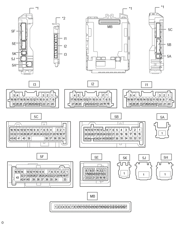
| *1 | Power Distribution Box Assembly | *2 | Main Body ECU (Multiplex Network Body ECU) |
Remove the main body ECU (multiplex network body ECU) from the power distribution box assembly.
for LHD: Click herePower Source / Network>POWER DISTRIBUTION>MAIN BODY ECU (for LHD)>REMOVAL
for RHD: Click herePower Source / Network>POWER DISTRIBUTION>MAIN BODY ECU (for RHD)>REMOVAL
Connect the power distribution box assembly connectors.
Measure the voltage and resistance according to the value(s) in the table below.
| Terminal No. (Symbol) | Terminal Description | Condition | Specified Condition |
|---|---|---|---|
| 5B-36 - Body ground | Ground | Always | Below 1 Ω |
| 5B-44 - Body ground | Ground | Always | Below 1 Ω |
| 5C-41 - Body ground | Ground | Always | Below 1 Ω |
| 5C-25 - Body ground | Ground | Always | Below 1 Ω |
| 5E-21 - Body ground | Battery power supply | Always | 11 to 14 V |
| 5E-23 - Body ground | Battery power supply | Always | 11 to 14 V |
| 5J-1 - Body ground | Battery power supply | Always | 11 to 14 V |
Install the main body ECU (multiplex network body ECU).
for LHD: Click herePower Source / Network>POWER DISTRIBUTION>MAIN BODY ECU (for LHD)>INSTALLATION
for RHD: Click herePower Source / Network>POWER DISTRIBUTION>MAIN BODY ECU (for RHD)>INSTALLATION
Measure the voltage and check for pulses according to the value(s) in the table below.
| Terminal No. (Symbol) | Terminal Description | Condition | Specified Condition |
|---|---|---|---|
| 5E-5 - Body ground | CXPI communication line | Ignition switch off | Below 1 V |
| Ignition switch ON | Pulse generation | ||
| 5E-6 - Body ground | Headlight unit assembly LH power supply |
·
15 seconds or more after ignition switch turned off
·
Taillights off |
9.5 to 14 V |
|
·
Ignition switch ON or within 15 seconds after ignition switch turned off
·
Taillights on |
Below 1 V | ||
| 5E-10 - Body ground | Headlight unit assembly RH power supply |
·
15 seconds or more after ignition switch turned off
·
Taillights off |
9.5 to 14 V |
|
·
Ignition switch ON or within 15 seconds after ignition switch turned off
·
Taillights on |
Below 1 V | ||
| 5E-15 - Body ground | IG power supply | Ignition switch off | Below 1 V |
| Ignition switch ON | 11 to 14 V | ||
| 5F-7 - Body ground | Taillights drive output | Taillights off | Below 1 V |
| Taillights on | 11 to 14 V | ||
| 5F-28 - Body ground*1 | Front fog lights drive output | Taillights on, fog light switch in off position | Below 1 V |
| Taillights on, fog light switch in front position | 11 to 14 V | ||
| 5F-30 - Body ground*2 | Rear fog lights drive output | Taillights on, fog light switch in off position | Below 1 V |
| Taillights on, fog light switch in rear position | 11 to 14 V | ||
| 5F-38 - Body ground | Back-up lights drive output | Ignition switch ON, reverse (R) not selected | Below 1 V |
| Ignition switch ON, reverse (R) selected | 11 to 14 V | ||
| I3-8 (CLTB) - I3-21 (CLTE) | Automatic light control sensor power supply output | Ignition switch ON | 11 to 14 V |
| I3-14 (AHBI) - Body ground*3 | Auto high beam switch signal input | Auto high beam switch off | 11 to 14 V |
| Auto high beam switch on | Below 1 V | ||
| I3-15 (AHID) - Body ground*3 | Auto high beam switch indicator drive output | Ignition switch ON, auto high beam switch off | 11 to 14 V |
| Ignition switch ON, auto high beam switch on | Below 1 V | ||
| I3-20 (CLTS) - Body ground | Automatic light control sensor signal input | Ignition switch off | Below 1 V |
| Ignition switch ON | Pulse generation (See waveform 1) | ||
| I3-26 (HEAD) - Body ground | Light control switch head position input | Light control switch not in head position | 11 to 14 V |
| Light control switch in head position | Below 1 V |
*1: w/ Front Fog Light
*2: w/ Rear Fog Light
*3: w/ Automatic High Beam System
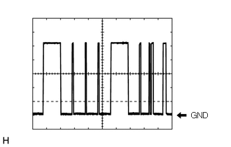
Waveform 1
| Item | Content |
|---|---|
| Tester Connection | I3-20 (CLTS) - Body ground |
| Tool Setting | 2 V/DIV., 10 ms./DIV. |
| Condition | Ignition switch ON |
- HINT:
-
The communication waveform changes according to the surrounding brightness.
CHECK COMBINATION METER ASSEMBLY
Click hereVehicle Interior>METER / GAUGE / DISPLAY>METER / GAUGE SYSTEM>TERMINALS OF ECU
CHECK FORWARD RECOGNITION CAMERA (w/ Automatic High Beam System)
Click hereADAS / AD>ADVANCED DRIVER ASSISTANCE SYSTEM>FRONT CAMERA SYSTEM>TERMINALS OF ECU
CHECK STEERING SENSOR