F33A-FTV ENGINE CONTROL ECD SYSTEM(w/ DPF) ECM Power Source Circuit
DESCRIPTION
When the ignition switch is turned to ON, battery power is supplied to the IGP terminal of the ECM and MREL is operated.
As a result, the EFI MAIN NO. 1 Relay contact closes and power is supplied to the +B and +B2 terminals of the ECM.
WIRING DIAGRAM
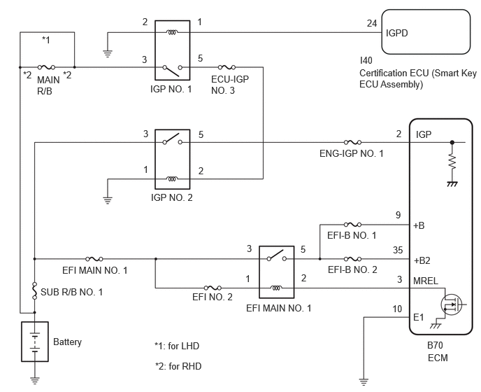
CAUTION / NOTICE / HINT
- NOTICE:
-
·
Inspect the fuses of circuits related to this system before performing the following inspection procedure.
·After replacing the ECM, the new ECM needs registration (Click here Engine / Hybrid System>F33A-FTV (ENGINE CONTROL)>ECD SYSTEM (w/ DPF)>REGISTRATION) and initialization (Click here Engine / Hybrid System>F33A-FTV (ENGINE CONTROL)>ECD SYSTEM (w/ DPF)>INITIALIZATION).
·After replacing the ECM and performing "LEARNING VALUES WRITE", select "PM Regenerate Mode" using Utility of the GTS to perform PM forced regeneration.
Click hereEngine / Hybrid System>F33A-FTV (EMISSION CONTROL)>EMISSION CONTROL SYSTEM>ON-VEHICLE INSPECTION
PROCEDURE
Disconnect the ECM connector.
Measure the resistance according to the value(s) in the table below.
- Standard Resistance:
-
Tester Connection Condition Specified Condition Click Location & Routing(B70)Location & Routingewd_type=routing;type=c;code=B70
B70-10 (E1) - Body ground Always Below 1 Ω
- Result:
-
Proceed to OK NG
OK
NG
Disconnect the ECM connector.
Turn the ignition switch to ON.
Measure the voltage according to the value(s) in the table below.
- Standard Voltage:
-
Tester Connection Condition Specified Condition Click Location & Routing(B70)Location & Routingewd_type=routing;type=c;code=B70
B70-2 (IGP) - Body ground Ignition switch ON 11 to 14 V
- Result:
-
Proceed to OK NG
OK
NG
Click hereEngine / Hybrid System>F33A-FTV (ENGINE CONTROL)>RELAY>ON-VEHICLE INSPECTION
- Result:
-
Proceed to OK NG
OK
NG
Disconnect the ECM connector.
Remove the EFI MAIN NO. 1 relay and EDU relay from the No. 3 engine room relay block and junction block assembly.
- HINT:
-
Remove the EDU relay connected between the checked terminals as the coil inside the relay influences the measurement value.
Remove the EFI MAIN NO. 2 relay, NOX relay, DCU relay and EFI MAIN NO. 3 relay from the No. 4 engine room relay block and junction block assembly.
- HINT:
-
Remove the EFI MAIN NO. 2 relay, NOX relay, DCU relay and EFI MAIN NO. 3 relay connected between the checked terminals as the coil inside the relay influences the measurement value.
Measure the resistance according to the value(s) in the table below.
- Standard Resistance:
-
Tester Connection Condition Specified Condition Click Location & Routing(B70)Location & Routingewd_type=routing;type=c;code=B70
EFI MAIN NO. 1 relay terminal 2 - B70-3 (MREL) Always Below 1 Ω EFI MAIN NO. 1 relay terminal 5 - B70-9 (+B) Always Below 1 Ω EFI MAIN NO. 1 relay terminal 5 - B70-35 (+B2) Always Below 1 Ω EFI MAIN NO. 1 relay terminal 2 or B70-3 (MREL) - Body ground and other terminals Always 10 kΩ or higher EFI MAIN NO. 1 relay terminal 5, B70-9 (+B) or B70-35 (+B2) - Body ground and other terminals Always 10 kΩ or higher
- Result:
-
Proceed to OK NG
OK
NG
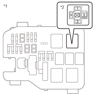
| *1 | No. 3 Engine Room Relay Block and Junction Block Assembly |
| *2 | EFI MAIN NO. 1 Relay |
Remove the EFI MAIN NO. 1 relay from the No. 3 engine room relay block and junction block assembly.
Measure the voltage according to the value(s) in the table below.
- Standard Voltage:
-
Tester Connection Condition Specified Condition EFI MAIN NO. 1 relay terminal 3 - Body ground Always 11 to 14 V EFI MAIN NO. 1 relay terminal 1 - Body ground Always 11 to 14 V
- Result:
-
Proceed to OK NG
OK
NG
Click hereEngine / Hybrid System>F33A-FTV (ENGINE CONTROL)>RELAY>ON-VEHICLE INSPECTION
- Result:
-
Proceed to OK NG
OK
NG
Disconnect the ECM connector.
Remove the IGP NO. 2 relay from the No. 4 engine room relay block and junction block assembly.
Measure the resistance according to the value(s) in the table below.
- Standard Resistance:
-
Tester Connection Condition Specified Condition Click Location & Routing(B70)Location & Routingewd_type=routing;type=c;code=B70
IGP NO. 2 relay terminal 5 - B70-2 (IGP) Always Below 1 Ω IGP NO. 2 relay terminal 5 or B70-2 (IGP) - Body ground and other terminals Always 10 kΩ or higher
- Result:
-
Proceed to OK NG
OK
NG
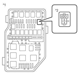
| *1 | No. 4 Engine Room Relay Block and Junction Block Assembly |
| *2 | IGP NO. 2 Relay |
Remove the IGP NO. 2 relay from the No. 4 engine room relay block and junction block assembly.
Measure the voltage according to the value(s) in the table below.
- Standard Voltage:
-
Tester Connection Condition Specified Condition IGP NO. 2 relay terminal 3 - Body ground Always 11 to 14 V
- Result:
-
Proceed to OK NG
OK
NG
Remove the IGP NO. 2 relay from the No. 4 engine room relay block and junction block assembly.
Measure the resistance according to the value(s) in the table below.
- Standard Resistance:
-
Tester Connection Condition Specified Condition IGP NO. 2 relay terminal 1 - Body ground Always Below 1 Ω
- Result:
-
Proceed to OK NG
OK
NG
Remove the IGP NO. 1 relay from the No. 1 engine room relay block and junction block assembly.
Remove the IGP NO. 2 relay from the No. 4 engine room relay block and junction block assembly.
Remove the IGP NO. 3 relay from the No. 1 luggage room relay block and junction block assembly.
- HINT:
-
Remove the IGP NO. 3 relay connected between the checked terminals as the coil inside the relay influences the measurement value.
Measure the resistance according to the value(s) in the table below.
- Standard Resistance:
-
Tester Connection Condition Specified Condition IGP NO. 1 relay terminal 5 - IGP NO. 2 relay terminal 2 Always Below 1 Ω IGP NO. 1 relay terminal 5 or IGP NO. 2 relay terminal 2 - Body ground and other terminals Always 10 kΩ or higher
- Result:
-
Proceed to OK NG
OK
NG
Click hereEngine / Hybrid System>F33A-FTV (ENGINE CONTROL)>RELAY>ON-VEHICLE INSPECTION
- Result:
-
Proceed to OK NG
OK
NG
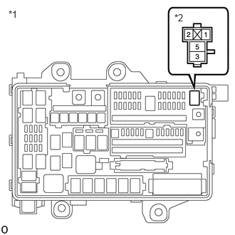
| *1 | No. 1 Engine Room Relay Block and Junction Block Assembly |
| *2 | IGP NO. 1 Relay |
Remove the IGP NO. 1 relay from the No. 1 engine room relay block and junction block assembly.
Measure the voltage according to the value(s) in the table below.
- Standard Voltage:
-
Tester Connection Condition Specified Condition IGP NO. 1 relay terminal 3 - Body ground Always 11 to 14 V
- Result:
-
Proceed to OK NG
OK
NG
Remove the IGP NO. 1 relay from the No. 1 engine room relay block and junction block assembly.
Measure the resistance according to the value(s) in the table below.
- Standard Resistance:
-
Tester Connection Condition Specified Condition IGP NO. 1 relay terminal 2 - Body ground Always Below 1 Ω
- Result:
-
Proceed to OK NG
OK
NG
Remove the IGP NO. 1 relay from the No. 1 engine room relay block and junction block assembly.
Disconnect the certification ECU (smart key ECU assembly) connector.
Measure the resistance according to the value(s) in the table below.
- Standard Resistance:
-
Tester Connection Condition Specified Condition Click Location & Routing(I40)Location & Routingewd_type=routing;type=c;code=I40
I40-24 (IGPD) - IGP NO. 1 relay terminal 1 Always Below 1 Ω I40-24 (IGPD) or IGP NO. 1 relay terminal 1 - Body ground and other terminals Always 10 kΩ or higher
- Result:
-
Proceed to OK NG
OK
NG