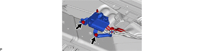
SUSPENSION CONTROL STABILIZER CONTROL VALVE(for Front Side) REMOVAL
CAUTION / NOTICE / HINT
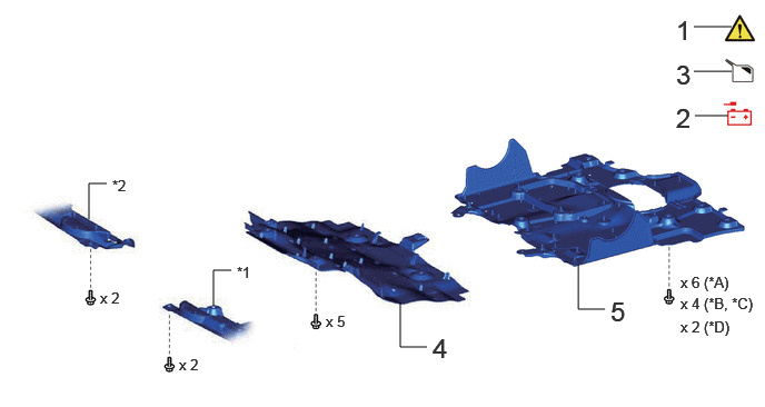
| Procedure | Part Name Code |

|

|

|
|
|---|---|---|---|---|---|
| 1 | PRECAUTION | - | ( ) |
- | - |
| 2 | DISCONNECT CABLE FROM NEGATIVE BATTERY TERMINAL | - | - | - | - |
| 3 | DRAIN SUSPENSION FLUID | - | - | () |
- |
| 4 | NO. 1 ENGINE UNDER COVER ASSEMBLY | 51410 | - | - | - |
| 5 | NO. 2 ENGINE UNDER COVER ASSEMBLY | 51420 | - | - | - |
| *A | for V35A-FTS, w/ Cover | *B | for V35A-FTS, w/o Cover |
| *C | for F33A-FTV, w/ Cover | *D | for F33A-FTV, w/o Cover |
| *1 | ENGINE SIDE COVER SUB-ASSEMBLY LH | *2 | ENGINE SIDE COVER SUB-ASSEMBLY RH |
| Procedure | Part Name Code |
|
|
|
|
|---|---|---|---|---|---|
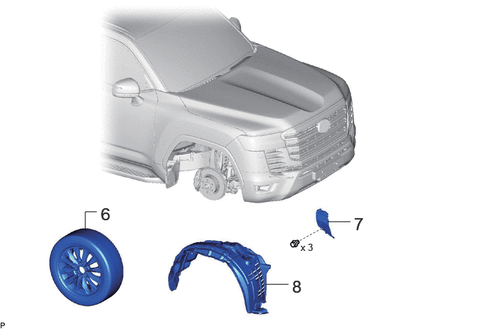
| 6 | FRONT WHEEL | - | - | ||
| 7 | FRONT FENDER APRON TRIM PACKING A | 53782 | - | - | - |
| 8 | FRONT FENDER SPLASH SHIELD SUB-ASSEMBLY RH | 53805 | - | - | - |
| Procedure | Part Name Code |
|
|
|
|
|---|---|---|---|---|---|
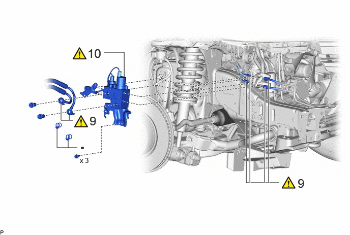
| 9 | FRONT STABILIZER CONTROL TUBE ASSEMBLY | - | () |
- | - |
| 10 | FRONT STABILIZER HOUSING SUB-ASSEMBLY | 48006 | () |
- | - |
| ● | Non-reusable part | - | - |
| Procedure | Part Name Code |
|
|
|
|
|---|---|---|---|---|---|
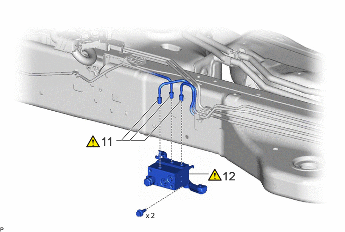
| 11 | FRONT STABILIZER CONTROL TUBE ASSEMBLY | - | () |
- | - |
| 12 | STABILIZER CONTROL VALVE SUB-ASSEMBLY | 48005 | () |
- | - |
CAUTION / NOTICE / HINT
The necessary procedures (adjustment, calibration, initialization, or registration) that must be performed after parts are removed and installed, or replaced during the front stabilizer housing sub-assembly and stabilizer control valve sub-assembly removal/installation are shown below.
| Replaced Part or Performed Procedure | Necessary procedures | Effect/Inoperative Function when Necessary Procedure not Performed | Link |
|---|---|---|---|
| Disconnect cable from negative (-) battery terminal | Memorize steering angle neutral point | Parking assist monitor system | () |
| Multi-terrain monitor system | () |
||
| Panoramic view monitor system | () |
- HINT:
-
·
When the cable is disconnected/reconnected to the battery terminal, systems temporarily stop operating. However, each system has a function that completes learning the first time the system is used.
-Learning completes when vehicle is driven
Effect/Inoperative Function When Necessary Procedures are not Performed Necessary Procedures Link Stop and start system Drive the vehicle until stop and start control is permitted (approximately 5 to 60 minutes) ( )Lighting system (EXT) Cornering lights Drive the vehicle straight ahead at 35 km/h (22 mph) or more for 5 seconds or more. ( )Pre-collision system Lane tracing assist system Lane tracing assist system Adaptive high beam system
-Learning completes when vehicle is operated normally
Effect/Inoperative Function When Necessary Procedures are not Performed Necessary Procedures Link Power back door system Fully close the back door by hand.
- HINT:
-
Initialization is not necessary if the above procedures are performed while the back door is closed.
( )Air conditioning system After the ignition switch is turned to ON, the servo motor and expansion valve standard position is recognized. -
PROCEDURE

 1. PRECAUTION
|
|
|
2.DISCONNECT CABLE FROM NEGATIVE BATTERY TERMINAL
for V35A-FTS:
for F33A-FTV:
3.DRAIN SUSPENSION FLUID
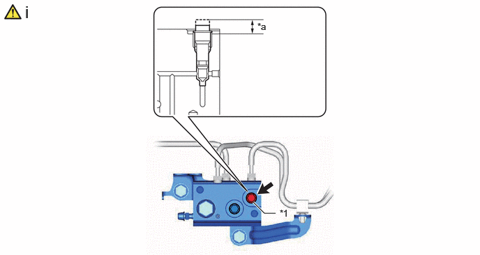
| *1 | Upper Shutter Valve | - | - |
| *a | 1.5 to 2.5 Turns | - | - |
Using an 8 mm socket wrench, loosen the upper shutter valve of the stabilizer control valve sub-assembly.
- NOTICE:
-
·
When loosening a shutter valve, loosen it 1.5 to 2.5 turns, but do not loosen it any more than that.
·As air may enter the system or fluid may spray out, do not remove the shutter valve.
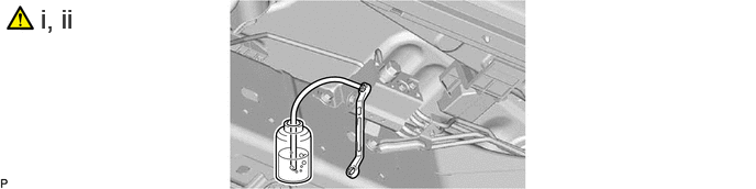
Loosen the bleeder plug of the stabilizer control valve sub-assembly and drain suspension fluid.
- CAUTION:
-
Be careful as the vehicle height will rapidly decrease when the bleeder plug of the stabilizer control valve sub-assembly is loosened.
- HINT:
-
·
Drain suspension fluid when performing operations related to the hydraulic circuits.
·Draining suspension fluid decreases suspension fluid pressure.
Tighten the bleeder plug.
- Torque:
- 8.3 N*m (85 kgf*cm, 73 in.*lbf)
51410 4.REMOVE NO. 1 ENGINE UNDER COVER ASSEMBLY
for V35A-FTS:
Click hereEngine / Hybrid System>V35A-FTS (LUBRICATION)>OIL PAN AND OIL LEVEL SENSOR>REMOVAL
for F33A-FTV:
Click hereEngine / Hybrid System>F33A-FTV (LUBRICATION)>OIL PAN AND OIL LEVEL SENSOR>REMOVAL
51420 5.REMOVE NO. 2 ENGINE UNDER COVER ASSEMBLY
for V35A-FTS:
Click hereEngine / Hybrid System>V35A-FTS (ENGINE MECHANICAL)>ENGINE ASSEMBLY>REMOVAL
for F33A-FTV:
Click hereEngine / Hybrid System>F33A-FTV (ENGINE MECHANICAL)>ENGINE ASSEMBLY>REMOVAL
6.REMOVE FRONT WHEEL
53782 7.REMOVE FRONT FENDER APRON TRIM PACKING A

53805 8.REMOVE FRONT FENDER SPLASH SHIELD SUB-ASSEMBLY RH
Use the same procedure as for the LH side.
Click hereVehicle Exterior>WIPER / WASHER>WASHER MOTOR>REMOVAL
9.DISCONNECT FRONT STABILIZER CONTROL TUBE ASSEMBLY
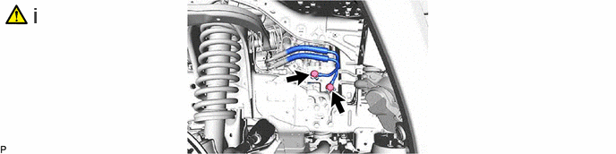
Remove the 2 union bolts and 2 gaskets, and disconnect the front stabilizer control tube assembly.
- NOTICE:
-
·
Do not kink or damage the front stabilizer control tube assembly.
·Do not allow any foreign matter such as dirt or dust to enter the front stabilizer control tube assembly from the connecting parts.
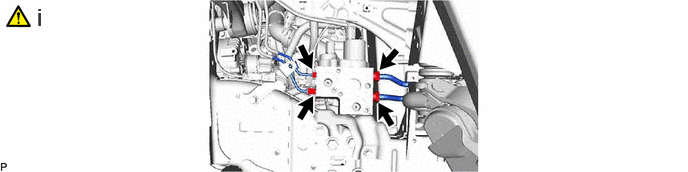
Using a union nut wrench, disconnect the front stabilizer control tube assembly.
- NOTICE:
-
·
Do not kink or damage the front stabilizer control tube assembly.
·Do not allow any foreign matter such as dirt or dust to enter the front stabilizer control tube assembly from the connecting parts.
48006 10.REMOVE FRONT STABILIZER HOUSING SUB-ASSEMBLY
|
|
|

11.DISCONNECT FRONT STABILIZER CONTROL TUBE ASSEMBLY
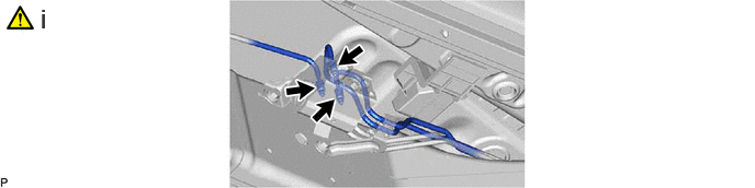
Using a union nut wrench, disconnect the front stabilizer control tube assembly.
- NOTICE:
-
·
Do not kink or damage the front stabilizer control tube assembly.
·Do not allow any foreign matter such as dirt or dust to enter the front stabilizer control tube assembly from the connecting parts.
48005 12.REMOVE STABILIZER CONTROL VALVE SUB-ASSEMBLY
|
|
|