THEFT DETERRENT / KEYLESS ENTRY ENTRY AND START SYSTEM(for Start Function) Fingerprint Authentication Failed and the Engine does not Start
DESCRIPTION
If fingerprint authentication fails and the engine does not start, there may be a malfunction between the certification ECU (smart key ECU assembly) and engine switch and a malfunction in the engine switch, or a dirty sensor.
CAUTION / NOTICE / HINT
- NOTICE:
-
·
When using the GTS with the ignition switch off, connect the GTS to the DLC3 and turn a courtesy light switch on and off at intervals of 1.5 seconds or less until communication between the GTS and the vehicle begins. Then select Model Code "KEY REGIST" under manual mode and enter the following menus: Body Electrical / Entry&Start(CAN). While using the GTS, periodically turn a courtesy light switch on and off at intervals of 1.5 seconds or less to maintain communication between the GTS and the vehicle.
·The entry and start system (for Start Function) uses the LIN communication system and CAN communication system. Inspect the communication function by following How to Proceed with Troubleshooting. Troubleshoot the entry and start system (for Start Function) after confirming that the communication systems are functioning properly.
·Before replacing the engine switch, refer to Service Bulletin.
·After repair, confirm that no DTCs are output by performing "DTC Output Confirmation Operation".
·When cleaning the surface of the sensor, use a soft, dry cloth without any fibers sticking out.
·The sensor is extremely sensitive to dryness and moisture. Be sure to clean your hands prior to performing registration.
PROCEDURE
Check for DTCs.
- Body Electrical > Entry&Start > Trouble Codes
- 50001 440
- Body Electrical > Main Body > Trouble Codes
- 50001 449
- Body Electrical > Combination Meter > Trouble Codes
- 50001 409
- Result:
-
Result Proceed to DTCs are not output A DTC is output. B
A
B
Using the GTS to read the Data List allows values or states of switches, sensors, actuators and other items to be read without removing any parts.
- Body Electrical > Entry&Start > Data List
-
Tester Display Measurement Item Range Normal Condition Diagnostic Note Fingerprint Authentication Data Fix Engine switch data status No/Yes No: Data not confirmed
Yes: Data confirmed-
- Body Electrical > Entry&Start > Data List
-
Tester Display Fingerprint Authentication Data Fix - 50003 440 153
- OK:
-
Fingerprint Authentication Data Fix is "Yes"
- Result:
-
Proceed to OK NG
OK
NG
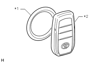
| *1 | Engine Switch |
| *2 | Electrical Key Transmitter Sub-assembly |
Check that the engine starts when the engine switch is operated while touching the electrical key transmitter sub-assembly (electrical key) to the surface of the engine switch.
- Result:
-
Result Proceed to The engine starts A The engine does not start B
A
B
Check whether the engine switch sensor is dirty.
- OK:
-
Sensor not dirty
- Result:
-
Proceed to OK NG
OK
NG
Disconnect and then reconnect the negative (-) battery terminal.
Perform fingerprint registration using a finger other than that of the customer and check that registration is normal.
- OK:
-
Registered normal
- Result:
-
Proceed to OK NG
OK
NG
Perform fingerprint registration using the customer's finger and check that registration is normal.
- HINT:
-
Perform fingerprint registration using the customer's finger and check that registration is normal.
- OK:
-
Registered normally
- Result:
-
Proceed to OK NG
OK
NG
Check that the engine starts using fingerprint authentication.
- Result:
-
Result Proceed to The engine starts A The engine does not start B
A
B
Perform fingerprint registration using the customer's finger and check that registration is normal.
- HINT:
-
Perform registration using a finger that has not been registered
- OK:
-
Registered normally
- Result:
-
Proceed to OK NG
OK
NG
Check that the engine starts using fingerprint authentication.
- Result:
-
Result Proceed to The engine starts A The engine does not start B
A
B
Using the GTS, delete all fingerprint information.
- Result:
-
Proceed to NEXT
NEXT
Perform fingerprint registration using the customer's finger and check that registration is normal.
- HINT:
-
Perform registration using the same finger that was registered
- OK:
-
Perform registration using the same finger that was registered
- Result:
-
Proceed to OK NG
OK
NG
Perform registration using the same finger that was registered
- Result:
-
Result Proceed to The engine starts A The engine does not start B
A
B
Replace the engine switch with a new one.
- HINT:
-
for 1GR-FE:
-
Click hereEngine / Hybrid System>1GR-FE (STARTING)>ENGINE SWITCH>REMOVAL
-
for V35A-FTS:
-
Click hereEngine / Hybrid System>V35A-FTS (STARTING)>ENGINE SWITCH>REMOVAL
-
for F33A-FTV:
-
Click hereEngine / Hybrid System>F33A-FTV (STARTING)>ENGINE SWITCH>REMOVAL
- Result:
-
Proceed to NEXT
NEXT
Register the ECU code registration.
- HINT:
-
Refer to Service Bulletin.
- Result:
-
Proceed to NEXT
NEXT
Perform fingerprint registration using the customer's finger and check that registration is normal.
- HINT:
-
Perform registration using the same finger that was registered
- OK:
-
Registered normally
- Result:
-
Proceed to OK NG
OK
NG
Check that the engine starts using fingerprint authentication.
- Result:
-
Result Proceed to The engine starts A The engine does not start B
A
B
Wipe off dirt from the engine switch sensor.
- NOTICE:
-
When cleaning the surface of the sensor, use a soft, dry cloth without any fibers sticking out.
- Result:
-
Proceed to NEXT
NEXT
Check that the engine starts using fingerprint authentication.
- Result:
-
Result Proceed to The engine starts A The engine does not start B
A
B
Disconnect the I39 connector of the certification ECU (smart key ECU assembly).
Disconnect the I75 connector of the engine switch.
Measure the resistance according to the value(s) in the table below.
- Standard Resistance:
-
Tester Connection Condition Specified Condition Click Location & Routing(I39,I75)Location & Routingewd_type=routing;type=c,c;code=I39,I75
I39-8 (LIN) - I75-4 (LIN) Always Below 1 Ω I39-8 (LIN) or I75-4 (LIN) - Body ground and other terminals Always 10 kΩ or higher
- Result:
-
Proceed to OK NG
OK
NG
Connect the I39 connector of the certification ECU (smart key ECU assembly).
Connect the I75 connector of the engine switch.
Measure the voltage according to the value(s) in the table below.
- Standard Voltage:
-
Tester Connection Condition Specified Condition Click Location & Routing(I75)Location & Routingewd_type=routing;type=c;code=I75
I75-10 (+B) - Body ground Always 11 to 14 V
- Result:
-
Proceed to OK NG
OK
NG
Measure the resistance according to the value(s) in the table below.
- Standard Resistance:
-
Tester Connection Condition Specified Condition Click Location & Routing(I75)Location & Routingewd_type=routing;type=c;code=I75
I75-3 (GND) - Body ground Always Below 1 Ω
- Result:
-
Proceed to OK NG
OK
NG