F33A-FTV ENGINE MECHANICAL CYLINDER HEAD DISASSEMBLY
CAUTION / NOTICE / HINT
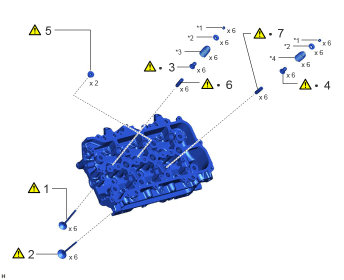
| Procedure | Part Name Code |

|

|

|
|
|---|---|---|---|---|---|
| 1 | INTAKE VALVE | 13711 | ( ) |
- | - |
| 2 | EXHAUST VALVE | 13715 | () |
- | - |
| 3 | INTAKE VALVE STEM OIL SEAL | 13711E | () |
- | - |
| 4 | EXHAUST VALVE STEM OIL SEAL | 13715A | () |
- | - |
| 5 | NO. 2 STRAIGHT SCREW PLUG LH WITH HEAD | 11117F | () |
- | - |
| 6 | NO. 2 INTAKE VALVE GUIDE BUSH | 11122B | () |
- | - |
| 7 | NO. 2 EXHAUST VALVE GUIDE BUSH | 11126B | () |
- | - |
| *1 | VALVE SPRING RETAINER LOCK | *2 | VALVE SPRING RETAINER |
| *3 | INTAKE VALVE COMPRESSION SPRING | *4 | EXHAUST VALVE COMPRESSION SPRING |
| ● | Non-reusable part | - | - |
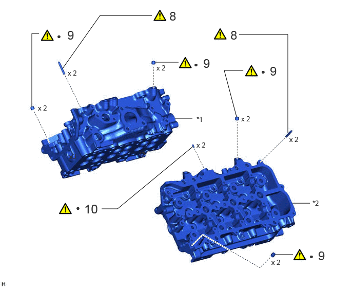
| Procedure | Part Name Code |
|
|
|
|
|---|---|---|---|---|---|
| 8 | STUD BOLT | - | () |
- | - |
| 9 | RING PIN | - | () |
- | - |
| 10 | STRAIGHT PIN | - | () |
- | - |
| *1 | CYLINDER HEAD SUB-ASSEMBLY RH | *2 | CYLINDER HEAD SUB-ASSEMBLY LH |
| ● | Non-reusable part | - | - |
CAUTION / NOTICE / HINT
The necessary procedures (adjustment, calibration, initialization, or registration) that must be performed after parts are removed, installed, or replaced during the cylinder head removal/installation are shown below.
| Replaced Part or Performed Procedure | Necessary Procedure | Effect/Inoperative Function when Necessary Procedure not Performed | Link |
|---|---|---|---|
| Battery terminal is disconnected/reconnected | Memorize steering angle neutral point | Parking assist monitor system | () |
| Multi-terrain monitor system | () |
||
| Panoramic view monitor system | () |
||
| Engine assembly | Perform road test to allow TCM to learn |
·
Large shift shock
·
Engine overruns |
() |
| Turbocharger sub-assembly | VN Turbo Offset Voltage Value Compensation |
·
Poor idle, etc.
·
Engine start function, etc. |
w/ DPF: ( ) w/o DPF: ( ) |
| Initialization | w/ DPF: ( ) w/o DPF: ( ) |
||
|
·
Diesel throttle body assembly
·
Electric EGR control valve assembly |
Initialization | - | |
| Automatic transmission fluid | ATF thermal degradation estimate reset | The value of the Data List item "ATF Thermal Degradation Estimate" is not estimated correctly. | () |
| Front bumper assembly (Including removal and installation) | Front television camera view adjustment | Panoramic view monitor system | () |
- HINT:
-
When the cable is disconnected/reconnected to the battery terminal, systems temporarily stop operating. However, each system has a function that completes learning the first time the system is used.
-
·
Learning completes when vehicle is driven
Effect/Inoperative Function When Necessary Procedures are not Performed Necessary Procedures Link Stop and start system Drive the vehicle until stop and start control is permitted (approximately 5 to 60 minutes). ( )Lighting system (EXT) Cornering lights Drive the vehicle straight ahead at 35 km/h (22 mph) or more for 5 seconds or more. ( )Pre-collision system Lane tracing assist system Lane departure alert system Adaptive high beam system
·Learning completes when vehicle is operated normally
Effect/Inoperative Function When Necessary Procedures are not Performed Necessary Procedures Link Power back door system Fully close the back door by hand.
- HINT:
-
Initialization is not necessary if the above procedures are performed while the back door is closed.
( )Air conditioning system After the ignition switch is turned to ON, the servo motor and expansion valve standard position is recognized. -
- HINT:
-
·
Use the same procedure for the Bank 1 side and Bank 2 side.
·The following procedure is for the Bank 2 side.
PROCEDURE

 13711 1.REMOVE INTAKE VALVE
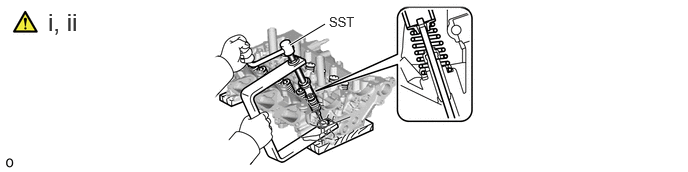
Using SST, compress each compression spring and remove the 6 cylinder head valve spring retainer locks.
- SST
-
09202-70020 (09202-01010, 09202-01020)
09202-00021
Remove the 6 valve spring retainers, 6 intake valve compression springs and 6 intake valves from the cylinder head sub-assembly.
- HINT:
-
Arrange the removed parts in the correct order.
13715 2.REMOVE EXHAUST VALVE
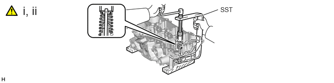
Using SST, compress each compression spring and remove the 6 cylinder head valve spring retainer locks.
- SST
-
09202-70020 (09202-01010, 09202-01020)
09202-00021
Remove the 6 valve spring retainers, 6 exhaust valve compression springs and 6 exhaust valves from the cylinder head sub-assembly.
- HINT:
-
Arrange the removed parts in the correct order.
13711E 3.REMOVE INTAKE VALVE STEM OIL SEAL
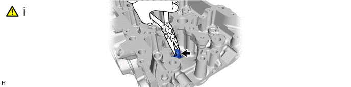
Using needle-nose pliers, remove the 6 intake valve stem oil seals.
13715A 4.REMOVE EXHAUST VALVE STEM OIL SEAL
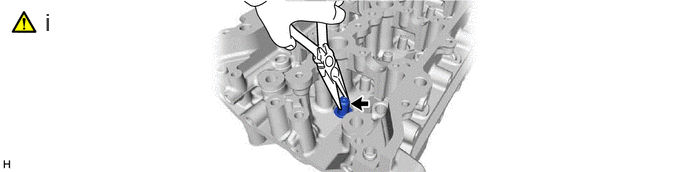
Using needle-nose pliers, remove the 6 exhaust valve stem oil seals.
11117F 5.REMOVE NO. 2 STRAIGHT SCREW PLUG WITH HEAD
|
|
|
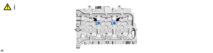
Using a 6 mm hexagon wrench, remove the No. 2 straight screw plugs with head.
11122B 6.REMOVE NO. 2 INTAKE VALVE GUIDE BUSH
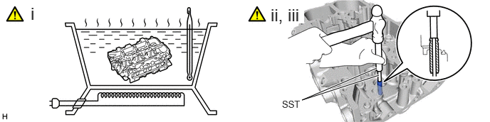
Heat the cylinder head sub-assembly to 80 to 100°C (176 to 212°F).
- CAUTION:
-
·
Do not touch the cylinder head sub-assembly without wearing protective gloves, as it may get very hot during operation.
·Be sure to wear protective gloves to avoid burns.
Place the cylinder head sub-assembly on wooden blocks.
- CAUTION:
-
Be sure to wear protective gloves.
Using SST and a hammer, tap out the No. 2 intake valve guide bushes.
- SST
-
09201-10000 (09201-01050)
09950-70010 (09951-07100)
09201-01055
11126B 7.REMOVE NO. 2 EXHAUST VALVE GUIDE BUSH
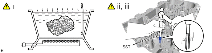
Heat the cylinder head sub-assembly to 80 to 100°C (176 to 212°F).
- CAUTION:
-
·
Do not touch the cylinder head sub-assembly without wearing protective gloves, as it may get very hot during operation.
·Be sure to wear protective gloves to avoid burns.
Place the cylinder head sub-assembly on wooden blocks.
- CAUTION:
-
Be sure to wear protective gloves.
Using SST and a hammer, tap out the No. 2 exhaust valve guide bushes.
- SST
-
09201-10000 (09201-01050)
09950-70010 (09951-07100)
09201-01055
8.REMOVE STUD BOLT
|
|
|
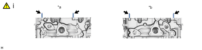
| *a | for Bank 1 | *b | for Bank 2 |
Using an E6 "TORX" socket wrench, remove the stud bolts.
9.REMOVE RING PIN
|
|
|
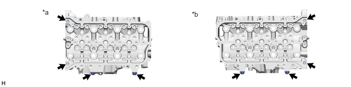
| *a | for Bank 1 | *b | for Bank 2 |
10.REMOVE STRAIGHT PIN
|
|
|
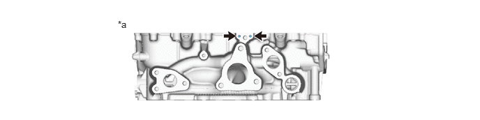
| *a | for Bank 2 | - | - |