F33A-FTV FUEL FUEL SUPPLY PUMP INSTALLATION
CAUTION / NOTICE / HINT
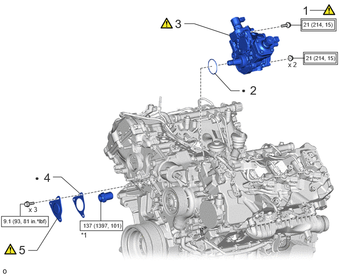
| Procedure | Part Name Code |

|

|

|
|
|---|---|---|---|---|---|
| 1 | PRECAUTION FOR WORK | - | ( ) |
- | - |
| 2 | INJECTION PUMP O-RING | 22100V | - | - | - |
| 3 | INJECTION OR SUPPLY PUMP ASSEMBLY | 22100 | () |
- | - |
| 4 | NO. 2 TIMING CHAIN COVER GASKET | 11329B | - | - | - |
| 5 | TIMING CHAIN COVER PLATE | 11324 | () |
- | - |
| *1 | SUPPLY PUMP DRIVE COUPLING | - | - |

|
Tightening torque for "Major areas involving basic vehicle performance such as moving/turning/stopping": N*m (kgf*cm, ft.*lbf) |

|
N*m (kgf*cm, ft.*lbf): Specified torque |
| ● | Non-reusable part | - | - |
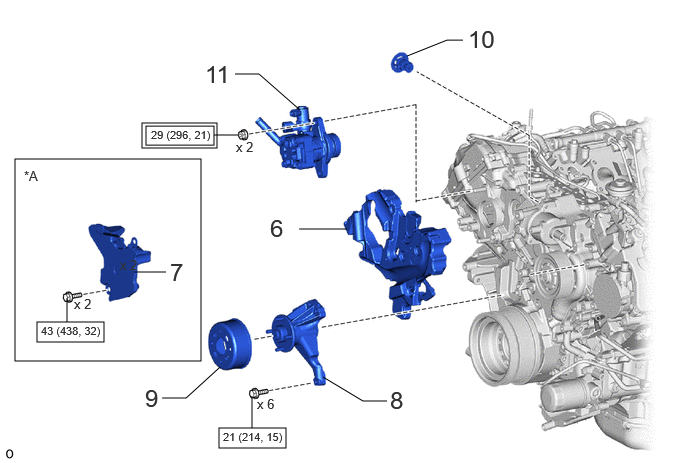
| Procedure | Part Name Code |
|
|
|
|
|---|---|---|---|---|---|
| 6 | TIMING CHAIN COVER INSULATOR | 11336B | - | - | - |
| 7 | NO. 2 TIMING GEAR CASE INSULATOR | 11338A | - | - | - |
| 8 | FAN BRACKET SUB-ASSEMBLY | 16307A | - | - | - |
| 9 | FAN PULLEY | 16371 | - | - | - |
| 10 | THERMOSTAT | 16331A | - | - | - |
| 11 | VANE PUMP ASSEMBLY | 44310 | - | - | - |
| *A | w/o Viscous Heater | - | - |
|
|
Tightening torque for "Major areas involving basic vehicle performance such as moving/turning/stopping": N*m (kgf*cm, ft.*lbf) |
|
N*m (kgf*cm, ft.*lbf): Specified torque |
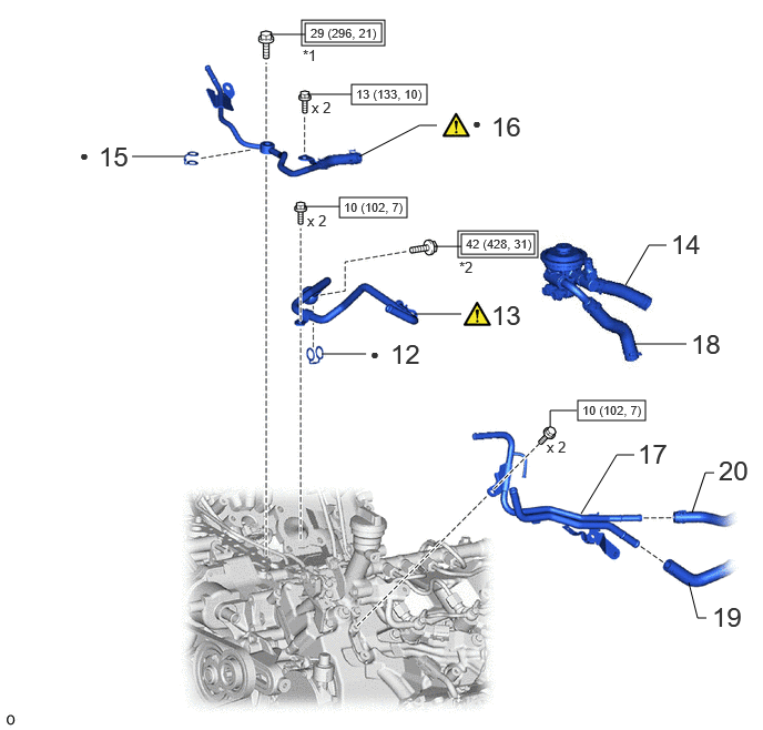
| Procedure | Part Name Code |
|
|
|
|
|---|---|---|---|---|---|
| 12 | GASKET | 23811K | - | - | - |
| 13 | NO. 1 FUEL PIPE | 23811G | () |
- | - |
| 14 | NO. 4 FUEL HOSE | 23282D | - | - | - |
| 15 | GASKET | 23801N | - | - | - |
| 16 | NO. 5 NOZZLE LEAKAGE PIPE | 23765 | () |
- | - |
| 17 | NO. 2 FUEL PIPE | 23812D | - | - | - |
| 18 | NO. 3 FUEL HOSE | 23274D | - | - | - |
| 19 | NO. 1 FUEL HOSE | 23271H | - | - | - |
| 20 | NO. 2 FUEL HOSE | 23273H | - | - | - |
| *1 | NOZZLE LEAKAGE PIPE SCREW | *2 | INJECTOR FOLLOW SCREW |
|
|
Tightening torque for "Major areas involving basic vehicle performance such as moving/turning/stopping": N*m (kgf*cm, ft.*lbf) |
|
N*m (kgf*cm, ft.*lbf): Specified torque |
| ● | Non-reusable part | - | - |
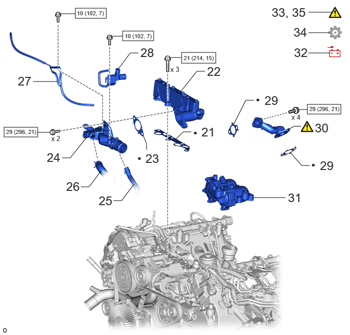
| Procedure | Part Name Code |
|
|
|
|
|---|---|---|---|---|---|
| 21 | TURBO OIL INLET GASKET | 15471 | - | - | - |
| 22 | TURBOCHARGER STAY | 17293 | - | - | - |
| 23 | WATER OUTLET HOUSING GASKET | 16343 | - | - | - |
| 24 | WATER OUTLET | 16331 | - | - | - |
| 25 | NO. 4 OIL COOLER HOSE | 15776A | - | - | - |
| 26 | WATER HOSE | 16571E | - | - | - |
| 27 | NO. 1 VACUUM TRANSMITTING PIPE SUB-ASSEMBLY | 25706 | - | - | - |
| 28 | NO. 1 VACUUM SWITCHING VALVE ASSEMBLY | 25860 | - | - | - |
| 29 | WATER OUTLET GASKET | 16341 | - | - | - |
| 30 | NO. 2 WATER OUTLET PIPE | 16335B | () |
- | - |
| 31 | DIESEL FUEL FILTER ASSEMBLY | 23300D | - | - | - |
| 32 | CONNECT CABLE TO NEGATIVE BATTERY TERMINAL | - | - | - | - |
| 33 | BLEED AIR FROM FUEL SYSTEM | - | () |
- | - |
| 34 | INITIALIZATION AFTER RECONNECTING BATTERY TERMINAL | - | - | - | () |
| 35 | INSPECT FOR FUEL LEAK | - | () |
- | - |
|
|
N*m (kgf*cm, ft.*lbf): Specified torque | ● | Non-reusable part |
PROCEDURE

 1. PRECAUTION FOR WORK
|
|
|
22100V 2.INSTALL INJECTION PUMP O-RING
22100 3.INSTALL INJECTION OR SUPPLY PUMP ASSEMBLY
|
|
|
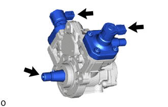
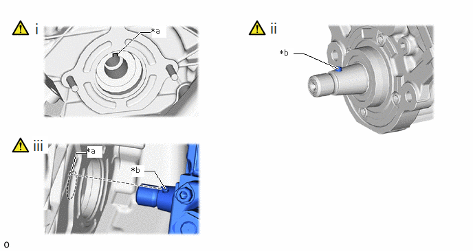
| *a | Groove | *b | Protrusion |
Check the position of the groove on the supply pump shaft sprocket.
Align the protrusion of the injection or supply pump assembly with the groove of the supply pump shaft sprocket.
Align the protrusions on the injection or supply pump assembly with the grooves on the supply pump shaft sprocket, and set the injection or supply pump assembly on the timing chain cover assembly.
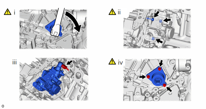
Turn the SST clockwise direction to install the injection or supply pump assembly to the timing chain or belt cover sub-assembly.
- SST
-
09241-11010
- HINT:
-
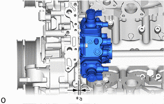 1.594,2 1.854,2.156 0.26,0.156 10 true *a
*a Gap
-
After tightening the part with SST, a gap of 2 to 3 mm in A shown in the illustration is normal.
Install the bolt and 2 nuts.
- Torque:
- 21 N*m (214 kgf*cm, 15 ft.*lbf)
Connect the connector to the injection or supply pump assembly.
Remove the 3 bolts and SST.
- SST
-
09241-11010
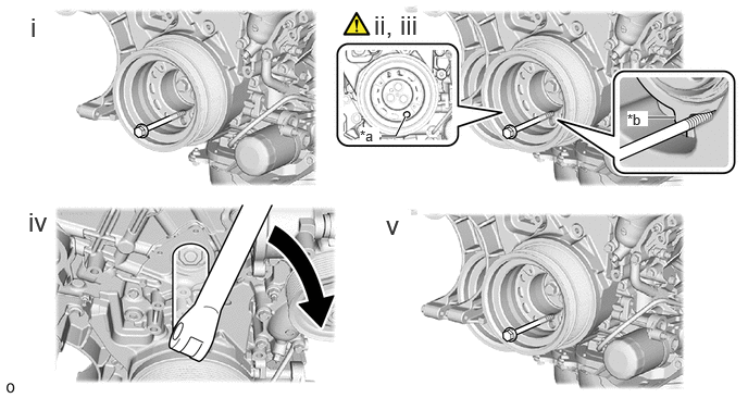
| *a | Service Hole | *b | Protrusion |
Remove the service bolt from the crankshaft pulley sub-assembly.
Turn the crankshaft pulley sub-assembly slightly counter clockwise direction, align the service hole of the crankshaft pulley sub-assembly with the position as shown in the illustration.
Install a service bolt and fix the crankshaft pulley sub-assembly.
| Length | 120 mm (4.72 in.) or more |
| Diameter | 14 mm (0.551 in.) |
| Pitch | 1.5 |
| Thread Length | 70 mm (2.76 in.) or more |
- HINT:
-
The crankshaft pulley sub-assembly is fixed by hooking a service bolt on the convex part of the timing chain cover sub-assembly.
Using a 27 mm deep socket wrench, tighten the supply pump drive coupling.
- Torque:
- 137 N*m (1397 kgf*cm, 101 ft.*lbf)
- NOTICE:
-
Tightening the supply pump drive coupling with more than the specified torque may damage the chain sub-assembly.
Remove the service bolt from the crankshaft pulley sub-assembly.
11329B 4.INSTALL NO. 2 TIMING CHAIN COVER GASKET
11324 5.INSTALL TIMING CHAIN COVER PLATE
|
|
|
- Torque:
- 9.1 N*m (93 kgf*cm, 7 ft.*lbf)
11336B 6.INSTALL TIMING CHAIN COVER INSULATOR
11338A 7.INSTALL NO. 2 TIMING GEAR CASE INSULATOR (w/o Viscous Heater)
- Torque:
- 43 N*m (438 kgf*cm, 32 ft.*lbf)
16307A 8.INSTALL FAN BRACKET SUB-ASSEMBLY
- Torque:
- 21 N*m (214 kgf*cm, 15 ft.*lbf)
16371 9.INSTALL FAN PULLEY
16331A 10.INSTALL THERMOSTAT
44310 11.CONNECT VANE PUMP ASSEMBLY
23811K 12.INSTALL GASKET
23811G 13.INSTALL NO. 1 FUEL PIPE
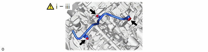
Temporarily install the No. 1 fuel pipe to the injection or supply pump assembly and cylinder head sub-assembly with the injector follow screw and 2 bolts.
Tighten the injector follow screw.
- Torque:
- 42 N*m (428 kgf*cm, 31 ft.*lbf)
Tighten the 2 bolts.
- Torque:
- 10 N*m (102 kgf*cm, 7 ft.*lbf)
23282D 14.CONNECT NO. 4 FUEL HOSE
23801N 15.INSTALL GASKET
23765 16.INSTALL NO. 5 NOZZLE LEAKAGE PIPE
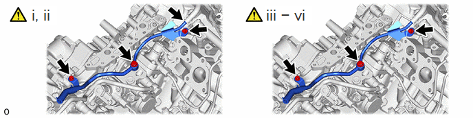
Connect the fuel hose to a new No. 5 nozzle leakage pipe, and slide the clamp to secure the hose.
Temporarily install the No. 5 nozzle leakage pipe to the injection or supply pump assembly and cylinder head sub-assembly with the nozzle leakage pipe screw and 2 bolts.
Tighten the nozzle leakage pipe screw.
- Torque:
- 5.0 N*m (51 kgf*cm, 44 in.*lbf)
Tighten the 2 bolts.
- Torque:
- 5.0 N*m (51 kgf*cm, 4 ft.*lbf)
Tighten the nozzle leakage pipe screw.
- Torque:
- 29 N*m (296 kgf*cm, 21 ft.*lbf)
Tighten the 2 bolts.
- Torque:
- 13 N*m (133 kgf*cm, 10 ft.*lbf)
23812D 17.INSTALL NO. 2 FUEL PIPE
- Torque:
- 10 N*m (102 kgf*cm, 7 ft.*lbf)
23274D 18.CONNECT NO. 3 FUEL HOSE
23271H 19.CONNECT NO. 1 FUEL HOSE
23273H 20.CONNECT NO. 2 FUEL HOSE
15471 21.INSTALL TURBO OIL INLET GASKET
17293 22.INSTALL TURBOCHARGER STAY
- Torque:
- 21 N*m (214 kgf*cm, 15 ft.*lbf)
16343 23.INSTALL WATER OUTLET HOUSING GASKET
16331 24.INSTALL WATER OUTLET
- Torque:
- 29 N*m (296 kgf*cm, 21 ft.*lbf)
15776A 25.CONNECT NO. 4 OIL COOLER HOSE
16571E 26.CONNECT WATER HOSE
25706 27.INSTALL NO. 1 VACUUM TRANSMITTING PIPE SUB-ASSEMBLY
- Torque:
- 10 N*m (102 kgf*cm, 7 ft.*lbf)
25860 28.INSTALL NO. 1 VACUUM SWITCHING VALVE ASSEMBLY
- Torque:
- 10 N*m (102 kgf*cm, 7 ft.*lbf)
16341 29.INSTALL WATER OUTLET GASKET
16335B 30.INSTALL NO. 2 WATER OUTLET PIPE
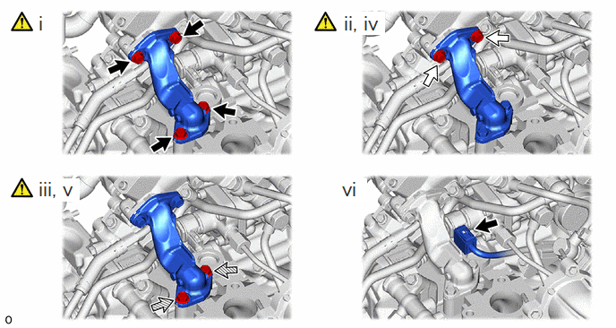

|
Bolt A |

|
Bolt B |
Temporarily install the No. 2 water outlet pipe to the turbocharger stay and cylinder head LH with the 4 bolts.
Tighten the bolt A until all of the threads make contact.
Tighten the bolt B until all of the threads make contact.
Tighten the bolt A.
- Torque:
- 29 N・m (296 kgf・cm, )
Tighten the bolt B.
- Torque:
- 29 N・m (296 kgf・cm, )
Connect the connector to the injection or supply pump assembly.
23300D 31.INSTALL DIESEL FUEL FILTER ASSEMBLY
32.CONNECT CABLE TO NEGATIVE BATTERY TERMINAL
33.BLEED AIR FROM FUEL SYSTEM
34. INITIALIZATION AFTER RECONNECTING BATTERY TERMINAL
Click hereGeneral>SETUP>WHEN DISCONNECTING OR RECONNECTING BATTERY TERMINAL>WORK PROCEDURE
- HINT:
-
When disconnecting and reconnecting the battery, there is an automatic learning function that completes learning when the respective system is used.
-
Click hereGeneral>SETUP>WHEN DISCONNECTING OR RECONNECTING BATTERY TERMINAL>AUTOMATIC LEARNING CHART
35.INSPECT FOR FUEL LEAK