1VD-FTV FUEL FUEL SUPPLY PUMP(w/o DPF) INSTALLATION
PROCEDURE

 22100 1.INSTALL FUEL SUPPLY PUMP ASSEMBLY
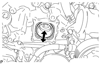
Check that the injection pump drive gear in the timing chain cover moves back and forth smoothly.
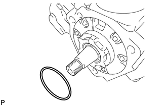
Install a new O-ring to the fuel supply pump assembly.
Apply a light coat of engine oil to the O-ring.
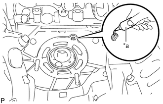
| *a | Adhesive |
Apply adhesive to 2 or more threads as shown in the illustration.
- Adhesive:
-
Toyota Genuine Adhesive 1344, Three Bond 1344 or equivalent
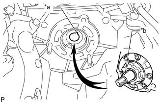
| *a | Groove |
| *b | Set Key |
Align the set key on the drive shaft with the groove of the injection pump drive gear.
- NOTICE:
-
Do not hold or carry the fuel supply pump assembly by holding the pipe.
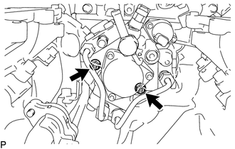
Temporarily install the fuel supply pump assembly with the 2 nuts.
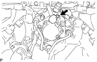
Using a 6 mm hexagon wrench, install the bolt.
- Torque:
- 21 N*m (214 kgf*cm, 15 ft.*lbf)
Tighten the 2 nuts.
- Torque:
- 21 N*m (214 kgf*cm, 15 ft.*lbf)
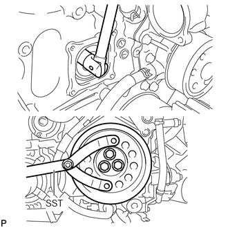
Using SST, hold the crankshaft pulley and install the set nut.
- SST
-
09960-10010 (09962-01000, 09963-01000)
- Torque:
- 68 N*m (693 kgf*cm, 50 ft.*lbf)
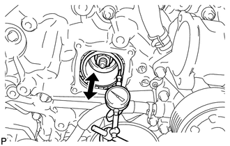
Move the pump drive shaft gear back and forth to check the thrust clearance of the supply pump drive shaft.
- Standard thrust clearance:
-
0.05 to 0.30 mm (0.00197 to 0.0118 in.)
If the clearance is not within the specified range, disassemble and reassemble the fuel supply pump assembly and pump drive shaft gear. Then repeat the step above.
Connect the fuel temperature sensor connector.
23811G 2.INSTALL NO. 1 FUEL PIPE
Install 2 new gaskets and the No. 1 fuel pipe to the fuel supply pump assembly with the union bolt.
- Torque:
- 17.2 N*m (175 kgf*cm, 13 ft.*lbf)
11324 3.INSTALL TIMING CHAIN COVER PLATE
Install a new gasket and the timing chain cover plate with the 4 bolts.
- Torque:
- 9.1 N*m (93 kgf*cm, 81 in.*lbf)
23705 4.INSTALL NO. 5 INJECTION PIPE SUB-ASSEMBLY
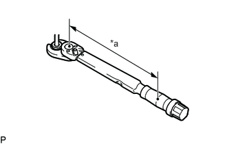
| *a | Torque Wrench Fulcrum Length |
Using a 17 mm union nut wrench, install a new No. 5 injection pipe sub-assembly to the fuel supply pump assembly with the union nuts.
- Torque:
- Specified tightening torque:
-
34 N*m (347 kgf*cm, 25 ft.*lbf)
Specified tightening torque
- HINT:
-
·
Calculate the torque wrench reading when changing the fulcrum length of the torque wrench.
Click hereGeneral>INTRODUCTION>REPAIR INSTRUCTION>PRECAUTION
·When using a union nut wrench (fulcrum length of 30 mm (1.1811 in.)) + torque wrench (fulcrum length of 180 mm (7.0866 in.)): 29.1 N*m (297 kgf*cm, 21 ft.*lbf)
23243C 5.INSTALL FUEL PUMP MOTOR WIRE
23920A 6.INSTALL FUEL COOLER
7.INSTALL COMMON RAIL ASSEMBLY
17940D 8.INSTALL INTERCOOLER ASSEMBLY
16331A 9.INSTALL THERMOSTAT
10.BLEED AIR FROM FUEL SYSTEM
11.ADD ENGINE COOLANT
12.CONNECT CABLE TO NEGATIVE BATTERY TERMINAL
13. FUEL SUPPLY PUMP INITIALIZATION
14.INSPECT FOR FUEL LEAK
15.INSPECT FOR OIL LEAK
16.INSPECT FOR COOLANT LEAK