HF1A TRANSFER / 4WD / AWD TRANSFER SHIFT LEVER ASSEMBLY INSTALLATION
PROCEDURE

 36331A 1.INSTALL NO. 2 TRANSFER SHIFT LEVER BOOT
Install a new No. 2 transfer shift lever boot to the transfer high and low shift lever assembly.
33554B 2.INSTALL TRANSFER SHIFT LEVER CAP
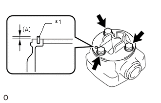
| *1 | Straight Pin |
Install a new straight pin to the transfer control shift lever retainer.
- Drive in depth (A):
-
3.0 to 4.0 mm (0.1182 to 0.1574 in.)
Install the transfer shift lever cap to the transfer control shift lever retainer with the 3 bolts.
- Torque:
- 29.4 N*m (300 kgf*cm, 22 ft.*lbf)
36360G 3.INSTALL TRANSFER HIGH AND LOW SHIFT LEVER ASSEMBLY
Install the transfer shift lever support to the transfer shift lever assembly.
Install the transfer high and low shift lever assembly to the transfer shift lever assembly.
36327 4.INSTALL TRANSFER SHIFT LEVER SHAFT
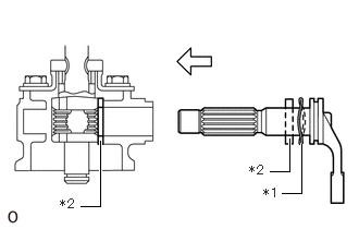
| *1 | Wave Washer |
| *2 | Transfer Shift Lever Bush |
Install the wave washer and a new transfer shift lever bush to the transfer shift lever shaft.
Set a new transfer shift lever bush and install the transfer shift lever shaft to the transfer shift lever assembly.
- NOTICE:
-
Align the splines so that the slotted pin holes of the transfer shift lever shaft and transfer shift lever support are aligned.
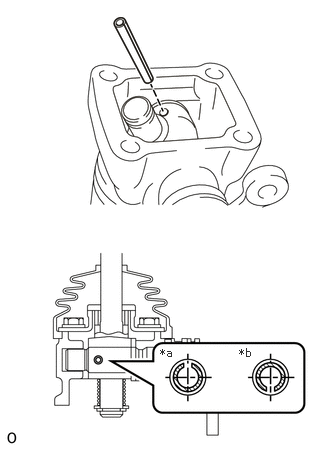
| *a | 90° |
| *b | 270° |
Check that the slotted pin holes of the transfer shift lever shaft and transfer shift lever support are aligned, and then tap in the slotted pin so that its slit is at a 90° +/-30° or 270° +/-30° angle to the central axis of the transfer shift lever shaft.
- NOTICE:
-
·
Tap in the slotted pin so that it is flush with the edge of the transfer shift lever support.
·When tapping in the slotted pin, do not hit down the wave washer more than necessary.
Install the transfer shift lever compression spring and plate washer to the transfer shift lever assembly.
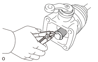
Using a snap ring expander, install a new front transfer drive shift lever hole snap ring to the transfer shift lever assembly.
36331 5.INSTALL TRANSFER SHIFT LEVER BOOT
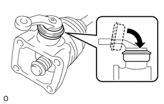
Install a new transfer shift lever boot to the transfer shift lever assembly.
- NOTICE:
-
Be careful of the installation direction of the transfer shift lever boot.
6.INSTALL TRANSFER SHIFT LEVER ASSEMBLY
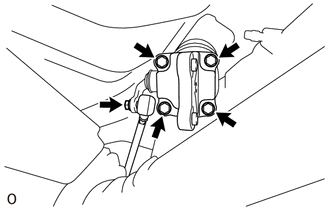
Connect the high and low shift rod sub-assembly to the transfer shift lever assembly with the washer and nut.
- HINT:
-
Temporarily install the washer and high and low shift rod sub-assembly.
Install the transfer control shift lever retainer bracket and new transfer control shift lever retainer gasket to the transfer shift lever assembly with the 4 bolts.
- Torque:
- 18.13 N*m (185 kgf*cm, 13 ft.*lbf)
- NOTICE:
-
Be careful of the installation direction of the transfer control shift lever retainer gasket.
Tighten the high and low shift rod sub-assembly to the specified torque.
- Torque:
- 11.76 N*m (120 kgf*cm, 9 ft.*lbf)
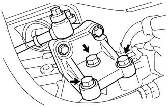
Align the positions of the 2 ring pins and install the transfer shift lever assembly with the 3 bolts.
- Torque:
- 37.24 N*m (380 kgf*cm, 27 ft.*lbf)
7.INSPECT AND ADJUST TRANSFER SHIFT LEVER ASSEMBLY
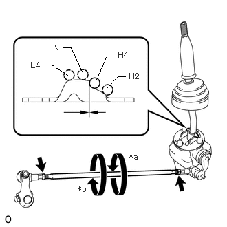
| *a | High and low shift rod sub-assembly expanding direction |
| *b | High and low shift rod sub-assembly contracting direction |
High and low shift rod sub-assembly adjustment
Heat the 2 joint nuts of the high and low shift rod sub-assembly.
- HINT:
-
Heat the joint nuts until the high and low shift rod sub-assembly can rotate freely.
When the transfer shift lever assembly is in the H4 position, adjust the length of the high and low shift rod sub-assembly so that the gap between the shift lever pin and transfer shift lever cap is 0 mm.
- HINT:
-
Heat the joint nuts until the high and low shift rod sub-assembly can rotate freely.
- NOTICE:
-
If the high and low shift rod sub-assembly is rotated or tightened excessively, the shift lever pin may not drop when shifting from the N position to the H4 position.
Transfer shift lever assembly operation confirmation
After adjusting the high and low shift rod sub-assembly, repeatedly shift between the H4 and N positions, and then check that the shift lever pin completely drops and the shift stopper from the H4 position to the N position is engaged.
- HINT:
-
·
Repeat the confirmation procedure 4 or 5 times.
·If the shift lever pin does not drop sufficiently when shifting from the N position to the H4 position, adjust the high and low shift rod sub-assembly and perform the confirmation procedure again.
Tighten the 2 joint nuts to the specified torque.
- Torque:
- 12.7 N*m (130 kgf*cm, 9 ft.*lbf)
58286 8.INSTALL NO. 1 SHIFT AND SELECT LEVER BOOT
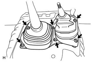
Install the No. 1 shift and select lever boot with the 6 bolts.
- Torque:
- 5.0 N*m (51 kgf*cm, 44 in.*lbf)
Return the floor carpet to its original position.
- HINT:
-
Install the front seat assembly if it was removed.
-
·
for Separate Seat Type with Inner Belt Attached: Click hereVehicle Interior>SEAT>FRONT SEAT ASSEMBLY(for Separate Seat Type with Inner Belt Attached)>INSTALLATION
·for Separate Seat Type without Inner Belt Attached: Click hereVehicle Interior>SEAT>FRONT SEAT ASSEMBLY (for Separate Seat Type without Inner Belt Attached)>INSTALLATION
·for Bench Seat Type: Click hereVehicle Interior>SEAT>FRONT SEAT ASSEMBLY(for Bench Seat Type)>INSTALLATION
36303 9.INSTALL SHIFT LEVER KNOB SUB-ASSEMBLY
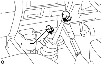
| *1 | Shift Lever Knob Sub-assembly (for Transfer Side) |
| *2 | Shift Lever Knob Sub-assembly (for Transmission Side) |
Twist the 2 shift lever knob sub-assembly in the direction indicated by the arrow to install it.
- NOTICE:
-
Install the shift lever knob sub-assembly in the correct position.
89441A 10.INSTALL DECELERATION SENSOR (w/ ABS)
89170 11.INSTALL AIRBAG SENSOR ASSEMBLY WITH AIRBAG SENSOR BRACKET (w/ Airbag System)
89179A 12.INSTALL AIRBAG SENSOR COVER
58811B 13.INSTALL CONSOLE BOX
58191 14.INSTALL FRONT FLOOR FOOTREST
for LHD: (Click hereVehicle Interior>INTERIOR PANELS / TRIM>FRONT FLOOR FOOTREST(for LHD)>INSTALLATION)
for RHD: (Click hereVehicle Interior>INTERIOR PANELS / TRIM>FRONT FLOOR FOOTREST(for RHD)>INSTALLATION)
62112A 15.INSTALL COWL SIDE TRIM SUB-ASSEMBLY LH
62111A 16.INSTALL COWL SIDE TRIM SUB-ASSEMBLY RH
- HINT:
-
Use the same procedure described for the LH side.
67914 17.INSTALL FRONT DOOR SCUFF PLATE LH
for 4 Door: (Click hereVehicle Interior>INTERIOR PANELS / TRIM>ROOF HEADLINING (for Double Cab)>INSTALLATION)
for 2 Door: (Click hereVehicle Interior>INTERIOR PANELS / TRIM>ROOF HEADLINING (for Single Cab)>INSTALLATION)
67913 18.INSTALL FRONT DOOR SCUFF PLATE RH
- HINT:
-
Use the same procedure described for the LH side.
19. CONNECT CABLE TO NEGATIVE BATTERY TERMINAL
20.PERFORM DIAGNOSTIC SYSTEM CHECK
21.CHECK SRS WARNING LIGHT