1VD-FTV FUEL FUEL COOLER(for Engine Room Side) INSTALLATION
PROCEDURE

 16295 1.INSTALL NO. 7 WATER BY-PASS HOSE
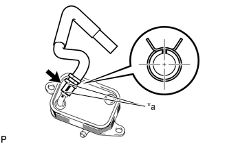
| *a | Marking |
Connect the No. 7 water by-pass hose to the fuel cooler, and slide the clamp to secure the hose.
- HINT:
-
·
Align the markings and connect the hose.
·Align the pinching portion of the clamp with the hose marking and connect the hose.
23920A 2.INSTALL FUEL COOLER
Install the fuel cooler with the 2 bolts.
- Torque:
- 10 N*m (102 kgf*cm, 7 ft.*lbf)
23763 3.INSTALL NO. 3 NOZZLE LEAKAGE PIPE
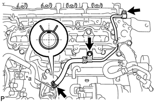
| *a | Marking |
Connect the No. 1 fuel hose to the fuel cooler, and slide the clamp to secure the hose.
- HINT:
-
·
Align the markings and connect the hose.
·Align the pinching portion of the clamp with the hose marking and connect the hose.
Install a new gasket and the No. 3 nozzle leakage pipe with the union bolt and bolt.
- Torque:
- for union bolt : 21 N*m (214 kgf*cm, 15 ft.*lbf)
- for bolt : 10 N*m (102 kgf*cm, 7 ft.*lbf)
23764A 4.INSTALL NO. 4 NOZZLE LEAKAGE PIPE
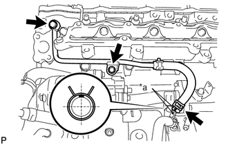
| *a | Marking |
Connect the No. 2 fuel hose to the fuel cooler, and slide the clamp to secure the hose.
- HINT:
-
·
Align the markings and connect the hose.
·Align the pinching portion of the clamp with the hose marking and connect the hose.
Install a new gasket and the No. 4 nozzle leakage pipe with the union bolt and bolt.
- Torque:
- for union bolt : 21 N*m (214 kgf*cm, 15 ft.*lbf)
- for bolt : 10 N*m (102 kgf*cm, 7 ft.*lbf)
16283 5.INSTALL NO. 6 WATER BY-PASS HOSE
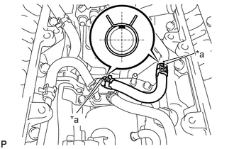
| *a | Marking |
Install the No. 6 water by-pass hose to the No. 1 water by-pass pipe and fuel cooler, and slide the 2 clamps to secure the hose.
- HINT:
-
·
Align the markings and connect the hose.
·Align the pinching portion of the clamp with the hose marking and connect the hose.
23274D 6.INSTALL NO. 3 FUEL HOSE
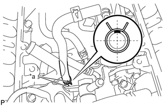
| *a | Marking |
Connect the No. 3 fuel hose to the fuel cooler, and slide the clamp to secure the hose.
- HINT:
-
·
Align the markings and connect the hose.
·Align the pinching portion of the clamp with the hose marking and connect the hose.
23805B 7.INSTALL NO. 5 FUEL PIPE SUB-ASSEMBLY
23243C 8.INSTALL FUEL PUMP MOTOR WIRE
9.INSTALL EGR VALVE WITH EGR COOLER (w/ EGR System)
10.INSTALL COMMON RAIL ASSEMBLY
17940D 11.INSTALL INTERCOOLER ASSEMBLY
12.BLEED AIR FROM FUEL SYSTEM
13.ADD ENGINE COOLANT
14.CONNECT CABLE TO NEGATIVE BATTERY TERMINAL
15. INITIALIZATION AFTER RECONNECTING BATTERY TERMINAL
- HINT:
-
When disconnecting and reconnecting the battery, there is an automatic learning function that completes learning when the respective system is used.
-
Click hereGeneral>SETUP>WHEN DISCONNECTING OR RECONNECTING BATTERY TERMINAL>AUTOMATIC LEARNING CHART
16.INSPECT FOR FUEL LEAK
17.INSPECT FOR OIL LEAK
18.INSPECT FOR COOLANT LEAK