Home › Brake › BRAKE CONTROL / DYNAMIC CONTROL SYSTEMS › BRAKE ACTUATOR (for LHD)
RM37H0E _54 Brake _096746 BRAKE CONTROL / DYNAMIC CONTROL SYSTEMS _0454011 BRAKE ACTUATOR(for LHD) A

BRAKE CONTROL / DYNAMIC CONTROL SYSTEMS  BRAKE ACTUATOR(for LHD)  INSTALLATION  


CAUTION / NOTICE / HINT
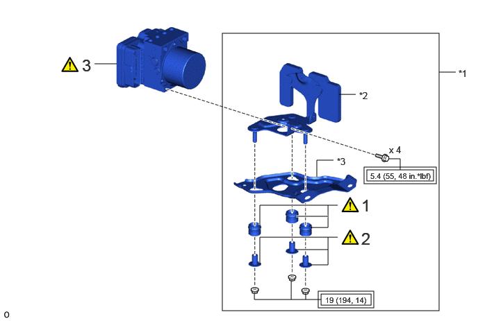
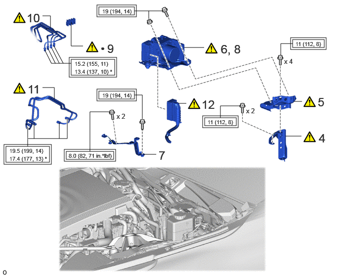
COMPONENTS (INSTALLATION)
C448785N02
3.333,0.5 6.583,4.667 3.25,4.167 5.5,2.552 6.5,2.719 1,0.167 5.458,2.51 6.542,2.76 1.083,0.25 4.771,4.375 5.604,4.625 0.833,0.25 4.813,4.417 5.563,4.583 0.75,0.167 1.417,0.958 1.75,0.958 false 4.458,3.75 4.917,3.75 true 3.896,3.948 3.896,3.563 3.896,3.563 5.063,3.563 true 4.667,3.979 4.917,3.979 4.917,3.979 4.917,3.563 false 3.896,3.385 3.896,3.083 3.896,3.083 5.063,3.083 true 4.667,3.417 4.917,3.417 4.917,3.417 4.917,3.083 false 4.438,3.25 4.917,3.25 true 6.583,1.083 6.833,1.083 false 5.083,1.417 5.333,1.417 false 4.75,2.656 4.75,2.406 4.75,2.406 5,2.406 false 5.833,2.385 6,2.385 6,2.385 6,2.552 false 3.813,4.417 3.813,4.5 3.813,4.5 4.813,4.5 false 4.365,4.219 4.365,4.5 false 4.583,4.417 4.583,4.5 false 1.229,0.833 1.729,1.167 0.5,0.333 18 false 3 5.417,3.438 5.917,3.771 0.5,0.333 18 false 2 5.417,2.938 5.917,3.271 0.5,0.333 18 false 1 5.833,2.167 6.25,2.417 0.417,0.25 10 false x 4 6.875,1.021 7.135,1.271 0.26,0.25 10 false *1 5.385,1.354 5.802,1.604 0.417,0.25 10 false *2 5.052,2.344 5.469,2.594 0.417,0.25 10 false *3 5.552,2.573 6.635,2.823 1.083,0.25 8 false 5.4 (55, 48 in.*lbf) 4.875,4.438 5.792,4.688 0.917,0.25 8 false 19 (194, 14)

Procedure Part Name Code
Z101186

Z101188

Z101187

1 BRAKE ACTUATOR BRACKET CUSHION 44547B (Click here) - -
2 NO. 1 BRAKE ACTUATOR CASE COLLAR 44521A (Click here) - -
3 BRAKE ACTUATOR ASSEMBLY 44510 (Click here) - -

*1 BRAKE ACTUATOR BRACKET ASSEMBLY *2 NO. 1 BRAKE ACTUATOR BRACKET
*3 NO. 2 BRAKE ACTUATOR BRACKET - -
V111893

Tightening torque for "Major areas involving basic vehicle performance such as moving/turning/stopping": N*m (kgf*cm, ft.*lbf) - -

C448783N01
4.313,2.479 4.979,2.646 0.667,0.167 4.271,2.438 5.021,2.688 0.75,0.25 1.5,1.25 2.417,1.583 0.917,0.333 1.458,1.208 2.458,1.625 1,0.417 0.125,3.083 1.042,3.417 0.917,0.333 0.083,3.042 1.083,3.458 1,0.417 1.396,3.188 2.396,3.354 1,0.167 2.083,1.917 2.833,2.083 0.75,0.167 2.042,1.875 2.875,2.125 0.833,0.25 6.167,0.833 6.833,1 0.667,0.167 6.125,0.792 6.875,1.042 0.75,0.25 1.354,3.146 2.438,3.396 1.083,0.25 2.083,0.146 2.833,0.313 0.75,0.167 2.042,0.104 2.875,0.354 0.833,0.25 4.646,2.479 4.646,2.229 4.646,2.229 5.063,2.229 false 0.896,0.333 1.063,0.333 1.063,0.333 1.063,0.583 false 1.5,0.469 1.5,0.969 1.5,0.969 1.75,0.969 false 0.938,1.042 1.083,1.333 1.083,1.333 1.5,1.333 false 1.083,1 1.25,1.333 false 1,1 1.167,1.333 false 1.125,0.948 1.333,1.333 false 0.583,2.667 0.583,3.083 true 1.417,2.5 1.417,2.917 1.417,2.917 0.583,2.917 true 1.25,2.917 1.25,2.583 false 0.719,2.917 0.719,2.583 false 2.313,2.354 1.896,2.354 1.896,2.354 1.896,3.188 false 2.833,2 3,2 3,2 3,2.5 false 5.917,1.167 5.917,0.917 5.917,0.917 6.167,0.917 false 2.833,0.229 3.417,0.229 false 3.135,0.229 3.135,0.396 false 0.896,1.844 1.146,1.844 1.146,1.844 1.146,2.094 false 3.76,2.177 3.927,2.177 false 6.198,2.135 6.365,2.135 false 6.021,2.865 6.354,2.865 false 3.885,1 4.302,1 false 3.042,3.25 3.292,3.25 false 4.375,2.5 5.208,2.75 0.833,0.25 8 false 11 (112, 8) 5.188,2.25 5.521,2.5 0.333,0.25 10 false x 2 5.99,1.208 6.323,1.458 0.333,0.25 10 false x 4 6.719,2.76 6.969,3.094 0.25,0.333 18 false 4 6.698,2 6.948,2.333 0.25,0.333 18 false 5 4.656,0.885 5.323,1.219 0.667,0.333 18 false 6, 8 3.344,3.125 3.594,3.458 0.25,0.333 18 false 7 2.458,2.365 2.792,2.615 0.333,0.25 10 false x 2 0.563,0.229 0.979,0.563 0.417,0.333 18 false 10 2.26,0.875 2.677,1.208 0.417,0.333 18 false 9 2.125,0.927 2.375,1.177 0.25,0.25 10 false ● 1.573,1.271 2.49,1.521 0.917,0.25 8 false 15.2 (155, 11) 1.573,1.438 2.49,1.688 0.917,0.25 8 false 13.4 (137, 10) * 0.198,3.104 1.115,3.354 0.917,0.25 8 false 19.5 (199, 14) 0.198,3.271 1.115,3.521 0.917,0.25 8 false 17.4 (177, 13) * 1.448,3.208 2.531,3.458 1.083,0.25 8 false 8.0 (82, 71 in.*lbf) 2.156,1.938 2.99,2.188 0.833,0.25 8 false 19 (194, 14) 6.229,0.854 7.063,1.104 0.833,0.25 8 false 11 (112, 8) 2.156,0.167 2.99,0.417 0.833,0.25 8 false 19 (194, 14) 0.583,1.729 1,2.063 0.417,0.333 18 false 11 4.25,2.052 4.667,2.385 0.417,0.333 18 false 12

Procedure Part Name Code
Z101186

Z101188

Z101187

4 NO. 3 BRAKE ACTUATOR BRACKET 44593 (Click here) - -
5 NO. 5 BRAKE ACTUATOR BRACKET 44595 (Click here) - -
6 TEMPORARILY INSTALL BRAKE ACTUATOR WITH BRACKET - (Click here) - -
7 WIRE HARNESS CLAMP BRACKET - - - -
8 INSTALL BRAKE ACTUATOR WITH BRACKET - (Click here) - -
9 BRAKE TUBE CLAMP - (Click here) - -
10 CONNECT BRAKE TUBE - (Click here) - -
11 INSTALL BRAKE TUBE - (Click here) - -
12 FRONT COMPARTMENT MAIN WIRE 82111C (Click here) - -

V111893

Tightening torque for "Major areas involving basic vehicle performance such as moving/turning/stopping": N*m (kgf*cm, ft.*lbf) * For use with a union nut wrench
● Non-reusable part - -

C448781N01
0.583,0.833 1.667,1 1.083,0.167 0.25,4.167 1.25,4.333 1,0.167 0.833,0.302 1.833,0.469 1,0.167 2.25,3.083 3,3.25 0.75,0.167 0.625,3.781 0.958,3.781 false 1.083,1.5 1.083,1.25 1.083,1.25 1.25,1.25 false 2.188,1.5 2.188,1.833 2.188,1.833 2.354,1.833 false 4.333,0.917 4.333,0.583 4.333,0.583 4.5,0.583 false 0.417,1.333 0.417,0.917 0.417,0.917 0.583,0.917 false 0.083,3 0.083,4.25 0.083,4.25 0.25,4.25 false 0.083,3 1.167,3 false 0.083,3.396 0.448,3.396 false 1.833,0.385 2.083,0.385 false 1.667,3.833 1.667,3.167 1.667,3.167 2.25,3.167 false 2,4.25 2.417,4.25 false 2,3.396 2,3.167 false 0.302,3.677 0.719,4.094 0.417,0.417 18 false 13 1.302,1.125 1.719,1.542 0.417,0.417 18 false 14 2.635,1.74 3.052,2.156 0.417,0.417 18 false 15 2.469,4.125 2.885,4.542 0.417,0.417 18 false 16 4.552,0.458 4.969,0.875 0.417,0.417 18 false 17 0.656,0.854 1.823,1.188 1.167,0.333 8 false 9.8 (100, 87 in.*lbf) 0.302,4.188 1.469,4.521 1.167,0.333 8 false 8.0 (82, 71 in.*lbf) 1.375,3.01 1.792,3.26 0.417,0.25 10 false x 2 0.885,0.323 2.052,0.656 1.167,0.333 8 false 8.0 (82, 71 in.*lbf) 2.313,3.104 3.146,3.438 0.833,0.333 8 false 49 (500, 36)

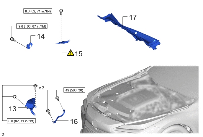
Procedure Part Name Code
Z101186

Z101188

Z101187

13 RELAY BLOCK - - - -
14 COOLER BRACKET - - - -
15 INSTALL FC CONVERTER POWER OUTLET CABLE (INVERTER WITH CONVERTER ASSEMBLY) G9200A (Click here) - -
16 FENDER APRON BRACE SUB-ASSEMBLY LH 53706A - -
17 COWL TOP VENTILATOR LOUVER SUB-ASSEMBLY 55708 - - -

V100146

N*m (kgf*cm, ft.*lbf): Specified torque - -

A481589N11
4.833,3 5.833,3.167 1,0.167 4.833,3.5 5.833,3.667 1,0.167 4.792,3.458 5.875,3.708 1.083,0.25 4.417,3.25 4.417,3.083 4.417,3.083 4.833,3.083 false 4.583,3.583 4.833,3.583 false 4.042,4.979 3.844,3.719 3.844,3.719 3.656,3.719 true 2.281,0.635 3.167,0.635 false 4.406,2.156 5.292,2.156 false 4.885,3.521 6.385,3.938 1.5,0.417 8 false 8.0 (82, 71 in.*lbf) 4.885,3.021 6.052,3.271 1.167,0.25 8 false 8.0 (82, 71 in.*lbf) 4.542,3.656 5,3.854 0.458,0.198 10 false x 2 3.313,3.625 3.865,3.979 0.552,0.354 18 false 18 4.146,1.469 4.604,1.667 0.458,0.198 10 false x 6 3.24,0.51 3.792,0.865 0.552,0.354 18 false 19 5.365,2.031 5.917,2.385 0.552,0.354 18 false 20

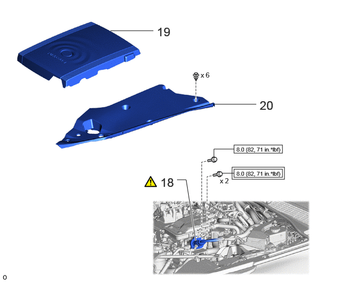
Procedure Part Name Code
Z101186

Z101188

Z101187

18 CONNECT FC CONVERTER POWER OUTLET CABLE (INVERTER WITH CONVERTER ASSEMBLY) G9200A (Click here) - -
19 FC STACK COVER SUB-ASSEMBLY 1A906 - - -
20 UPPER RADIATOR SUPPORT SEAL 53292A - - -

V111893

Tightening torque for "Major areas involving basic vehicle performance such as moving/turning/stopping": N*m (kgf*cm, ft.*lbf)
V100146

N*m (kgf*cm, ft.*lbf): Specified torque

C455569N01
6.438,0.219 6.854,0.219 false 6.438,0.583 6.854,0.583 false 6.448,1 6.781,1 false 6.479,1.396 6.813,1.396 false 1.792,0.833 2.125,0.833 false 5.698,0.479 6.615,0.813 0.917,0.333 18 false 21, 25 6.125,0.104 6.625,0.521 0.5,0.417 18 false 27 5.302,0.875 6.552,1.292 1.25,0.417 18 false 24, 26, 28 6.177,1.281 6.594,1.698 0.417,0.417 18 false 23 1.5,0.708 2,1.125 0.5,0.417 18 false 22

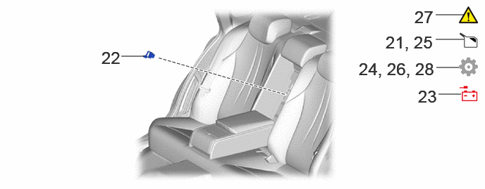
Procedure Part Name Code
Z101186

Z101188

Z101187

21 FILL RESERVOIR WITH BRAKE FLUID - - - -
22 SERVICE PLUG GRIP G3834 - - -
23 CONNECT CABLE TO NEGATIVE AUXILIARY BATTERY TERMINAL - - - -
24 UPDATE ECU SECURITY KEY - - - (Click here)
25 BLEED BRAKE SYSTEM - - (Click here) -
26 PERFORM INITIALIZATION AND CALIBRATION - - - (Click here)
27 CHECK AND CLEAR DTC - - - -
28 INITIALIZATION AFTER RECONNECTING BATTERY TERMINAL - - - (Click here)

PROCEDURE

Hide 44547B 1.INSTALL BRAKE ACTUATOR BRACKET CUSHION

Z101186

HINT:

Perform this procedure only when replacement of the brake actuator bracket cushions is necessary.


Hide 44521A 2.INSTALL NO. 1 BRAKE ACTUATOR CASE COLLAR

Z101186

NOTICE:

Make sure that the No. 1 brake actuator case collar is in full contact with the brake actuator bracket cushion.


HINT:

Perform this procedure only when replacement of the No. 1 brake actuator case collars is necessary.


Torque:
19 N*m (194 kgf*cm, 14 ft.*lbf)

Hide 44510 3.INSTALL BRAKE ACTUATOR ASSEMBLY

Z101186

NOTICE:
·

Do not remove the hole plugs of a new brake actuator assembly before connecting the brake tubes because the brake actuator assembly is filled with brake fluid.

·

Do not hold the brake actuator assembly by the connector.

·

Do not drop the brake actuator assembly when carrying it.


a.
C448800N01
4.063,1.063 4.229,1.313 0.167,0.25 10 true 1 0.417,0.052 1.167,0.385 0.75,0.333 18 false i, ii 4.26,0.198 4.427,0.448 0.167,0.25 10 false 2 2.958,1.031 3.125,1.281 0.167,0.25 10 false 3 3.563,1.698 3.729,1.896 0.167,0.198 10 true 4

i.

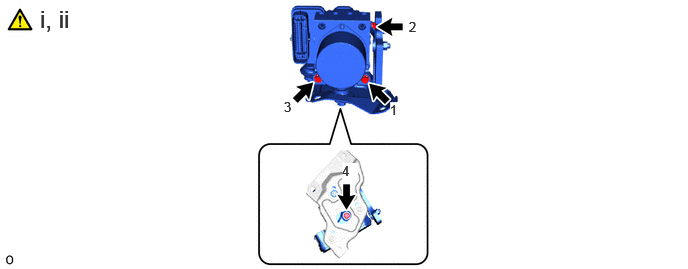
Temporarily install the brake actuator assembly to the brake actuator bracket assembly with the 4 bolts.


ii.

Install the brake actuator assembly to the brake actuator bracket assembly with the 4 bolts in the order shown in the illustration.

Torque:
5.4 N*m (55 kgf*cm, 48 in.*lbf)


Hide 44593 4.INSTALL NO. 3 BRAKE ACTUATOR BRACKET

Z101186

HINT:

Perform this procedure only when replacement of the No. 3 brake actuator bracket is necessary.


Torque:
11 N*m (112 kgf*cm, 8 ft.*lbf)

Hide 44595 5.INSTALL NO. 5 BRAKE ACTUATOR BRACKET

Z101186

HINT:

Perform this procedure only when replacement of the No. 5 brake actuator bracket is necessary.


a.
C448797N01
0.417,0.063 1.083,0.396 0.667,0.333 18 false i, ii 3.333,0.333 3.49,0.531 0.156,0.198 10 true 1 4.198,0.302 4.354,0.5 0.156,0.198 10 true 3 4.354,0.635 4.51,0.833 0.156,0.198 10 true 2 2.833,1.354 2.99,1.552 0.156,0.198 10 true 4

i.

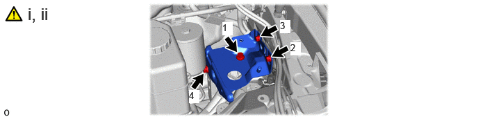
Temporarily install the No. 5 brake actuator bracket to the body with the 4 bolts.


ii.

Install the No. 5 brake actuator bracket to the body with the 4 bolts in the order shown in the illustration.

Torque:
11 N*m (112 kgf*cm, 8 ft.*lbf)


Hide 6.TEMPORARILY INSTALL BRAKE ACTUATOR WITH BRACKET

Z101186

NOTICE:
·

Do not kink or damage the brake tubes.

·

Do not allow any foreign matter such as dirt or dust to enter the brake tubes from the connecting parts.

·

Be careful not to allow any brake fluid to enter the connector.

·

Do not hold the brake actuator with bracket by the connector.

·

Do not drop the brake actuator with bracket when carrying it.


HINT:

Temporarily installl the brake actuator with bracket while avoiding the brake tubes.


a.
C448794


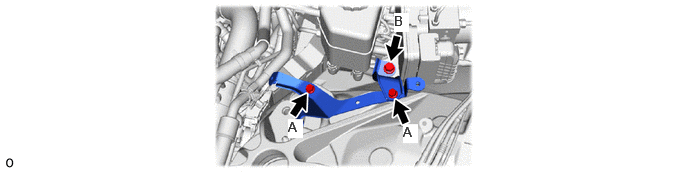
Hide 7.INSTALL WIRE HARNESS CLAMP BRACKET

a.
C448787N01
4.198,1.292 4.354,1.49 0.156,0.198 10 true A 3,1.24 3.156,1.438 0.156,0.198 10 true A 4.104,0.135 4.26,0.333 0.156,0.198 10 true B

Torque:
Bolt A : 8.0 N*m (82 kgf*cm, 71 in.*lbf)
Bolt B : 19 N*m (194 kgf*cm, 14 ft.*lbf)


Hide 8.INSTALL BRAKE ACTUATOR WITH BRACKET

Z101186

NOTICE:
·

Do not kink or damage the brake tubes.

·

Do not allow any foreign matter such as dirt or dust to enter the brake tubes from the connecting parts.

·

Be careful not to allow any brake fluid to enter the connector.

·

Do not hold the brake actuator with bracket by the connector.


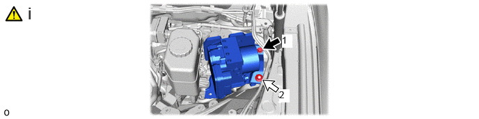
a.
C448795N01
4.219,0.521 4.375,0.719 0.156,0.198 10 true 1 4.177,1.344 4.333,1.542 0.156,0.198 10 true 2 0.417,0.052 1.25,0.385 0.833,0.333 18 false i

i.

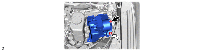
Tighten the bolt and nut in the order shown in the illustration.

Torque:
19 N*m (194 kgf*cm, 14 ft.*lbf)


Hide 9.INSTALL BRAKE TUBE CLAMP

Z101186

NOTICE:

Do not kink or damage the brake tubes.


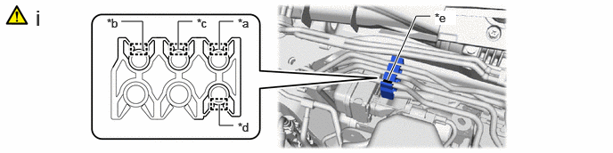
a.
C455714C01
4.531,0.938 4.865,0.188 4.865,0.188 5.031,0.188 true 2.563,0.583 2.563,0.25 2.563,0.25 2.729,0.25 true 2.083,0.583 2.083,0.25 2.083,0.25 2.25,0.25 true 1.667,0.583 1.667,0.25 1.667,0.25 1.417,0.25 true 2.563,1.219 2.563,1.469 2.563,1.469 2.729,1.469 true 2.781,0.188 3.115,0.438 0.333,0.25 10 false *a 1.25,0.188 1.583,0.438 0.333,0.25 10 false *b 2.302,0.188 2.552,0.438 0.25,0.25 10 false *c 2.781,1.406 3.115,1.656 0.333,0.25 10 false *d 5.083,0.125 5.333,0.292 0.25,0.167 10 true *e 0.417,0.063 0.75,0.396 0.333,0.333 18 false i
*a To Front Wheel Cylinder Assembly RH *b To Front Wheel Cylinder Assembly LH
*c To Rear Wheel Cylinder Assembly RH *d To Rear Wheel Cylinder Assembly LH
*e Paint Mark - -


i.

Engage the 4 clamps to install a new brake tube clamp so that it is at the center of the paint mark as shown in the illustration.


Hide 10.CONNECT BRAKE TUBE

Z101186

NOTICE:
·

Do not kink or damage the brake tubes.

·

Do not allow any foreign matter such as dirt or dust to enter the brake tube from the connecting parts.


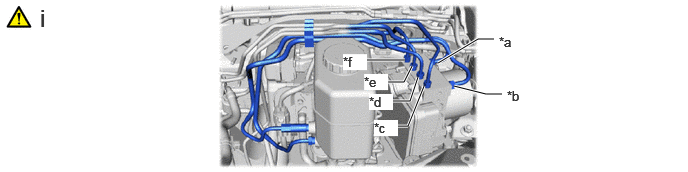
a.
C453656C01
4.563,0.656 4.979,0.406 4.979,0.406 5.146,0.406 true 4.729,0.896 5.063,0.979 5.063,0.979 5.229,0.979 true 4.083,1.313 4.25,1.313 4.25,1.313 4.417,0.896 true 4.021,1.052 4.271,1.052 4.271,1.052 4.354,0.802 true 3.958,0.854 4.208,0.854 4.208,0.854 4.292,0.688 true 3.719,0.625 4.219,0.625 true 5.198,0.354 5.615,0.604 0.417,0.25 10 false *a 5.281,0.917 5.615,1.167 0.333,0.25 10 false *b 3.896,1.25 4.146,1.417 0.25,0.167 10 true *c 3.844,0.979 4.094,1.146 0.25,0.167 10 true *d 3.792,0.771 4.042,0.938 0.25,0.167 10 true *e 3.573,0.563 3.823,0.729 0.25,0.167 10 true *f 0.417,0.042 0.75,0.375 0.333,0.333 18 false i
*a From 1st Chamber of Brake Booster with Master Cylinder Assembly *b From 2nd Chamber of Brake Booster with Master Cylinder Assembly
*c To Front Disc Brake Cylinder Assembly RH *d To Front Disc Brake Cylinder Assembly LH
*e To Rear Disc Brake Cylinder Assembly RH *f To Rear Disc Brake Cylinder Assembly LH


i.

Temporarily tighten the 6 brake tubes to the correct position on the brake actuator assembly as shown in the illustration.


b.
C448793C01
4.469,2.208 4.552,2.375 4.552,2.375 4.635,2.375 false 3.729,2.396 4.042,2.552 0.313,0.156 10 false *a 4.688,2.313 5.021,2.563 0.333,0.25 10 false *b 0.427,0.063 0.677,0.396 0.25,0.333 18 false i
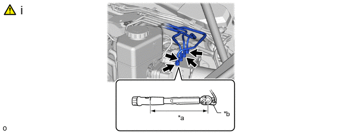
*a Torque Wrench Fulcrum Length *b Union Nut Wrench


i.

Using a union nut wrench, fully tighten the 4 brake tubes.

Torque:
Specified tightening torque : 15.2 N*m (155 kgf*cm, 11 ft.*lbf)

HINT:
·

Calculate the torque wrench reading when changing the fulcrum length of the torque wrench.

Click hereGeneral>INTRODUCTION>REPAIR INSTRUCTION>PRECAUTION

·

When using a union nut wrench (fulcrum length of 22 mm (0.866 in.)) + torque wrench (fulcrum length of 162 mm (6.38 in.)):

13.4 N*m (137 kgf*cm, 10 ft.*lbf)


Hide 11.INSTALL BRAKE TUBE

Z101186

NOTICE:
·

Do not kink or damage the brake tubes.

·

Do not allow any foreign matter such as dirt or dust to enter the brake tube from the connecting parts.


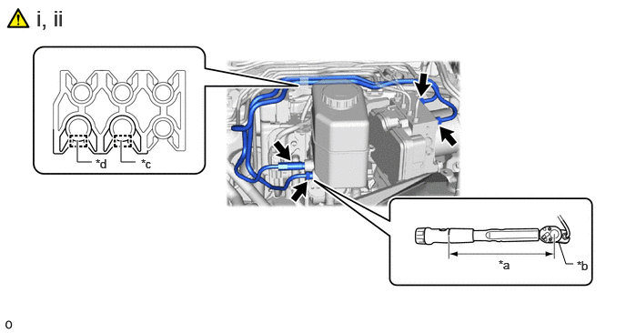
a.
C448790C01
6.396,2.771 6.479,3.021 6.479,3.021 6.563,3.021 false 0.885,1.604 0.885,1.854 0.885,1.854 1.052,1.854 true 1.385,1.604 1.385,1.854 1.385,1.854 1.552,1.854 true 5.708,2.948 6.021,3.104 0.313,0.156 10 false *a 6.604,2.958 6.938,3.125 0.333,0.167 10 false *b 0.417,0.063 1.25,0.396 0.833,0.333 18 false i, ii 1.615,1.792 1.844,2.042 0.229,0.25 10 false *c 1.094,1.792 1.344,2.042 0.25,0.25 10 false *d
*a Torque Wrench Fulcrum Length *b Union Nut Wrench
*c From 1st Chamber of Brake Booster with Master Cylinder Assembly *d From 2nd Chamber of Brake Booster with Master Cylinder Assembly


i.

Using a union nut wrench, fully tighten the 2 brake tubes.

Torque:
Specified tightening torque : 19.5 N*m (199 kgf*cm, 14 ft.*lbf)

HINT:
·

Calculate the torque wrench reading when changing the fulcrum length of the torque wrench.

Click hereGeneral>INTRODUCTION>REPAIR INSTRUCTION>PRECAUTION

·

When using a union nut wrench (fulcrum length of 20 mm (0.787 in.)) + torque wrench (fulcrum length of 162 mm (6.378 in.)):

17.4 N*m (177 kgf*cm, 13 ft.*lbf)


ii.

Engage the 2 clamps to install the 2 brake tubes.


Hide 82111C 12.CONNECT FRONT COMPARTMENT MAIN WIRE

Z101186

NOTICE:
·

Make sure that the connector is locked securely.

·

Make sure that the actuator connector can be connected smoothly.

·

Do not allow water, oil or dirt to enter the connector.


Hide 13.INSTALL RELAY BLOCK

Torque:
8.0 N*m (82 kgf*cm, 71 in.*lbf)

Hide 14.INSTALL COOLER BRACKET

Torque:
9.8 N*m (100 kgf*cm, 87 in.*lbf)

Hide G9200A 15.INSTALL FC CONVERTER POWER OUTLET CABLE (INVERTER WITH CONVERTER ASSEMBLY)

Z101186

CAUTION:

Wear insulated gloves.


Torque:
8.0 N*m (82 kgf*cm, 71 in.*lbf)

Hide 53706A 16.INSTALL FENDER APRON BRACE SUB-ASSEMBLY LH

Torque:
49 N*m (500 kgf*cm, 36 ft.*lbf)

Hide 55708 17.INSTALL COWL TOP VENTILATOR LOUVER SUB-ASSEMBLY

Hide G9200A 18.CONNECT FC CONVERTER POWER OUTLET CABLE (INVERTER WITH CONVERTER ASSEMBLY)

Z101186

Click here(Click here)

Hide 1A906 19.INSTALL FC STACK COVER SUB-ASSEMBLY

Hide 53292A 20.INSTALL UPPER RADIATOR SUPPORT SEAL

Hide 21.FILL RESERVOIR WITH BRAKE FLUID

Hide 23.CONNECT CABLE TO NEGATIVE AUXILIARY BATTERY TERMINAL

Hide 25.BLEED BRAKE SYSTEM

Hide 26.PERFORM INITIALIZATION AND CALIBRATION


b.

for Electric Parking Brake System:

Click hereBrake>PARKING BRAKE>ELECTRIC PARKING BRAKE SYSTEM>UTILITY


Hide 27. CHECK AND CLEAR DTC

Hide 28. INITIALIZATION AFTER RECONNECTING BATTERY TERMINAL

Click hereGeneral>SETUP>WHEN DISCONNECTING OR RECONNECTING BATTERY TERMINAL>WORK PROCEDURE

HINT:

When disconnecting and reconnecting the battery, there is an automatic learning function that completes learning when the respective system is used.

Click hereGeneral>SETUP>WHEN DISCONNECTING OR RECONNECTING BATTERY TERMINAL>AUTOMATIC LEARNING CHART