Q710 HYBRID TRANSMISSION / TRANSAXLE ELECTRONIC SHIFT LEVER SYSTEM P1765A2 Sub Battery Module System Voltage Low
DESCRIPTION
When 11 seconds after turning the ignition switch to ON (READY), the shift control supply power source is supplied to the BUB terminal of the shift control ECU.
| DTC No. | Detection Item | DTC Detection Condition | Trouble Area | Warning Indicate | DTC Output from | Priority |
|---|---|---|---|---|---|---|
| P1765A2 | Sub Battery Module System Voltage Low | The ignition switch is ON (READY) and auxiliary battery voltage is 10 V or higher, BUB terminal voltage (ECU recognition value) is below 1 V continuously for 3 seconds or more
(1 trip detection logic) |
·
Shift control supply ·
Shift control ECU ·
Wire harness or connector |
·
Master Warning -
Comes on ·
Multi-information Display Error Message -
Displayed |
EV | A |
CONFIRMATION DRIVING PATTERN
- HINT:
-
After repair has been completed, clear the DTC and then check that the vehicle has returned to normal by performing the All Readiness check procedure.
-
Click hereDrivetrain>Q710 (HYBRID TRANSMISSION / TRANSAXLE)>ELECTRONIC SHIFT LEVER SYSTEM>UTILITY
Turn the ignition switch to ON (READY) and wait for 5 seconds or more.
WIRING DIAGRAM
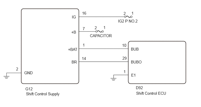
CAUTION / NOTICE / HINT
- NOTICE:
- ·
The vehicle is equipped with a shift control supply. Therefore, ensure there is no power being supplied to the vehicle when disconnecting or reconnecting the connector of the shift control ECU and when removing or installing the shift control ECU.
Click hereDrivetrain>Q710 (HYBRID TRANSMISSION / TRANSAXLE)>ELECTRONIC SHIFT LEVER SYSTEM>PRECAUTION
·Inspect the fuses for circuits related to this system before performing the following inspection procedure.
PROCEDURE
Pre-procedure1
None
Procedure1
Read the freeze frame data of DTC P1765A2.
- Powertrain > EV > Trouble Codes
- 50001 397
- Powertrain > EV > DTC(P1765A2) > Freeze Frame Data
-
Tester Display Sub Battery Module Backup Status (Gear Shift Control Module) - 50040 397 576 P1765A2
- Result:
Result Proceed to The value of Sub Battery Module Backup Status (Gear Shift Control Module) is not Sub Battery Module Fail Safe A The value of Sub Battery Module Backup Status (Gear Shift Control Module) is Sub Battery Module Fail Safe B
Post-procedure1
Turn the ignition switch off.
A
B
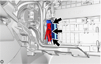
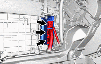
Check the connector connections and contact pressure of the relevant terminals for the shift control ECU connectors.
- HINT:
- OK:
The connectors are connected securely and there are no contact pressure problems.
- Result:
Proceed to OK NG
OK
NG
Pre-procedure1
Disconnect the D92 shift control ECU connector.
Turn the ignition switch to ON.
Procedure1
Measure the voltage according to the value(s) in the table below.
- Standard Voltage:
Tester Connection Condition Specified Condition Click Location & Routing(D92)Location & Routingewd_type=routing;type=c;code=D92
Click Connector(D92)Instrument Panel>Instrument Panel Wire>Shift Control ECUewd_type=component;type=c;code=D92;pinno=10
D92-10 (BUB) - Body ground 11 seconds after turning the ignition switch to ON 8 to 15.4 V
- NOTICE:
- ·
Turning the ignition switch to ON with the connector disconnected causes other DTCs to be stored. Clear the DTCs after performing this inspection.
·Measuring with the shift control supply connector connected.
- Result:
Proceed to OK NG
Post-procedure1
Turn the ignition switch off.
Reconnect the D92 shift control ECU connector.
OK
NG
Disconnect the D92 shift control ECU connector.
Disconnect the G12 shift control supply connector.
Remove the IG2 P NO.2 fuse from the luggage room relay block.
Remove the CAPACITOR fuse from the luggage room relay block.
Measure the resistance according to the value(s) in the table below.
- Standard Resistance:
Tester Connection Condition Specified Condition Click Location & Routing(G12,D92)Location & Routingewd_type=routing;type=c,c;code=G12,D92
Click Connector(G12)Instrument Panel>Floor Wire>Shift Control Supplyewd_type=component;type=c;code=G12;pinno=1,16,7,2
Click Connector(D92)Instrument Panel>Instrument Panel Wire>Shift Control ECUewd_type=component;type=c;code=D92;pinno=10
G12-1 (+BAT) - D92-10 (BUB) Always Below 1 Ω G12-16 (IG) - IG2 P NO.2 fuse terminal 2 Always Below 1 Ω CAPACITOR fuse terminal 2 - G12-7 (+B) Always Below 1 Ω G12-2 (GND) - Body ground Always Below 1 Ω G12-1 (+BAT) or D92-10 (BUB) - Body ground and other terminals Always 10 kΩ or higher G12-16 (IG) or IG2 P NO.2 fuse terminal 2 - Body ground Always 10 kΩ or higher CAPACITOR fuse terminal 2 or G12-7 (+B) - Body ground and other terminals Always 10 kΩ or higher
Install the CAPACITOR fuse.
Install the IG2 P NO.2 fuse.
Reconnect the G12 shift control supply connector.
Reconnect the D92 shift control ECU connector.
- Result:
Proceed to OK NG
OK
for LHD: Click hereDrivetrain>Q710 (HYBRID TRANSMISSION / TRANSAXLE)>SHIFT CONTROL POWER SUPPLY (for LHD)>REMOVAL
for RHD: Click hereDrivetrain>Q710 (HYBRID TRANSMISSION / TRANSAXLE)>SHIFT CONTROL POWER SUPPLY (for RHD)>REMOVAL
NG
Pre-procedure1
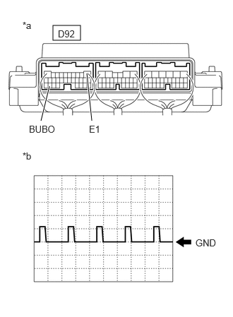
| *a | Component with harness connected
(Shift Control ECU) |
| *b | Waveform
(Shift control supply signal) |
Connect an oscilloscope between the shift control ECU terminals specified in the table below.
Procedure1
Turn the ignition switch to ON and measure the waveform.
- Standard Voltage:
Tester Connection Condition Specified Condition Click Location & Routing(D92)Location & Routingewd_type=routing;type=c;code=D92
Click Connector(D92)Instrument Panel>Instrument Panel Wire>Shift Control ECUewd_type=component;type=c;code=D92;pinno=29,1
D92-29 (BUBO) - D92-1 (E1) Ignition switch ON 10 V/DIV, 10 ms/DIV
- Result:
Result Proceed to The waveform appears A The waveform does not appear B
- NOTICE:
-
Turning the ignition switch to ON with the connector disconnected causes other DTCs to be stored. Clear the DTCs after performing this inspection.
Post-procedure1
Turn the ignition switch off.
A
for LHD: Click hereDrivetrain>Q710 (HYBRID TRANSMISSION / TRANSAXLE)>SHIFT CONTROL POWER SUPPLY (for LHD)>REMOVAL
for RHD: Click hereDrivetrain>Q710 (HYBRID TRANSMISSION / TRANSAXLE)>SHIFT CONTROL POWER SUPPLY (for RHD)>REMOVAL
B
Pre-procedure1
Disconnect the D92 shift control ECU connector.
Disconnect the G12 shift control supply connector.
Procedure1
Measure the resistance according to the value(s) in the table below.
- Standard Resistance:
Tester Connection Condition Specified Condition Click Location & Routing(G12,D92)Location & Routingewd_type=routing;type=c,c;code=G12,D92
Click Connector(G12)Instrument Panel>Floor Wire>Shift Control Supplyewd_type=component;type=c;code=G12;pinno=1,14
Click Connector(D92)Instrument Panel>Instrument Panel Wire>Shift Control ECUewd_type=component;type=c;code=D92;pinno=10,29
G12-1 (+BAT) - D92-10 (BUB) Always Below 1 Ω G12-14 (BR) - D92-29 (BUBO) Always Below 1 Ω G12-1 (+BAT) or D92-10 (BUB) - Body ground Always 10 kΩ or higher G12-14 (BR) or D92-29 (BUBO) - Body ground Always 10 kΩ or higher
- Result:
Proceed to OK NG
Post-procedure1
Reconnect the D92 shift control ECU connector.
Reconnect the G12 shift control supply connector.
OK
NG