FUEL TUBE JOINT(for Inlet Side) REMOVAL
CAUTION / NOTICE / HINT
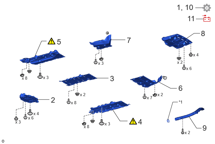
| Procedure | Part Name Code | 
|

|

|
|
|---|---|---|---|---|---|
| 1 | PRECAUTION | - | - | - | ( ) |
| 2 | REAR NO. 4 FLOOR BOARD SUB-ASSEMBLY | 58404B | - | - | - |
| 3 | REAR NO. 3 FLOOR BOARD SUB-ASSEMBLY | 58403L | - | - | - |
| 4 | NO. 2 FLOOR BOARD SUB-ASSEMBLY | 58402K | ()
|
- | - |
| 5 | NO. 1 FLOOR BOARD SUB-ASSEMBLY | 58401M | ()
|
- | - |
| 6 | REAR FLOOR SIDE MEMBER COVER LH | 57628E | - | - | - |
| 7 | REAR FLOOR SIDE MEMBER COVER RH | 57627G | - | - | - |
| 8 | NO. 1 FLOOR UNDER COVER | 58398F | - | - | - |
| 9 | NO. 3 FC EXHAUST PIPE | 17DB3 | - | - | - |
| 10 | PRESSURE RELEASE OPERATION | - | - | - | ()
|
| 11 | DISCONNECT CABLE FROM NEGATIVE AUXILIARY BATTERY TERMINAL | - | - | - | - |
| *1 | HOSE CLAMP | - | - |
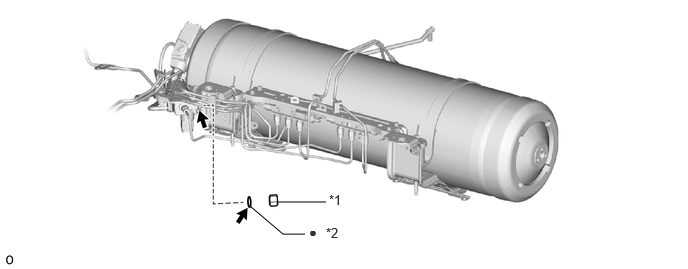
| *1 | NO. 1 HYDROGEN SUPPLY REGULATOR PLUG | *2 | O-RING |
| ● | Non-reusable part | 
|
TOYOTA Genuine FC Grease |
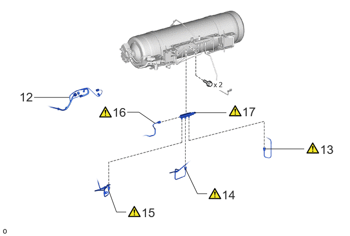
| Procedure | Part Name Code |
|
|
|
|
|---|---|---|---|---|---|
| 12 | FLOOR WIRE | 82161 | - | - | - |
| 13 | NO. 2 HYDROGEN TANK TUBE | 77BA2 | ()
|
- | - |
| 14 | NO. 4 HYDROGEN TANK TUBE | 77BA4 | ()
|
- | - |
| 15 | NO. 1 HYDROGEN TANK TUBE | 77BA1 | ()
|
- | - |
| 16 | NO. 3 HYDROGEN TANK TUBE | 77BA3 | ()
|
- | - |
| 17 | HYDROGEN TANK TUBE JOINT ASSEMBLY | 77BC0 | ()
|
- | - |
CAUTION / NOTICE / HINT
The necessary procedures (adjustment, calibration, initialization, or registration) that must be performed after parts are removed, installed, or replaced during the tube joint (for Inlet Side) removal/installation are shown below.
| Replacement Part or Procedure | Necessary Procedure | Effects/Inoperative when not Performed | Link |
|---|---|---|---|
| Disconnect cable from negative auxiliary battery terminal | Memorize steering angle neutral point | Parking assist monitor system | ()
|
| Panoramic view monitor system | ()
|
- HINT:
-
When the cable is disconnected/reconnected to the auxiliary battery terminal, systems temporarily stop operating. However, each system has a function that completes learning the first time the system is used.
- ·
Learning completes when vehicle is driven
Effect/Inoperative Function When Necessary Procedures are not Performed Necessary Procedures Link Lane tracing assist system Drive the vehicle straight ahead at 35 km/h (22 mph) or more for 5 seconds or more. ( )
Pre-collision system Adaptive high beam system
·Learning completes when vehicle is operated normally
Effect/Inoperative Function When Necessary Procedures are not Performed Necessary Procedures Link Air conditioning system After the ignition switch is turned to ON, the servo motor and expansion valve standard position is recognized. -
- CAUTION:
- ·
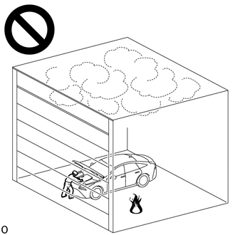
Work procedures must be performed in an area with good ventilation (airflow) where hydrogen gas will not accumulate, and flames or other things that could act as ignition sources must not be present.
·Accumulated hydrogen gas could ignite, resulting in a serious accident.
·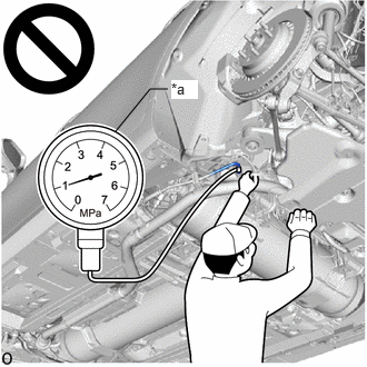 1.083,1.229 1.406,0.833 1.406,0.833 1.573,0.833 false 1.604,0.75 1.854,0.927 0.25,0.177 10 true *a
*a When inside of piping is pressurized
Do not install or remove any hydrogen system components without first performing depressurization procedures.
·The highly pressurized hydrogen gas inside the hydrogen tank assembly could blow out, resulting in a serious accident.
·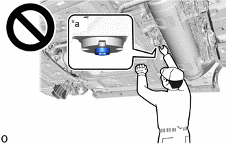 1.083,0.271 1.323,0.469 0.24,0.198 10 true *a
*a Manual Valve Open
Do not perform depressurization procedures when the manual valve of the hydrogen tank assembly is open.
·The highly pressurized hydrogen gas inside the hydrogen tank assembly could blow out, resulting in a serious accident.
·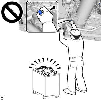
When performing depressurization, do not perform procedures by hand without wearing protective glasses and gloves.
·The highly pressurized hydrogen gas inside the hydrogen tank assembly could blow out, resulting in a serious accident.
·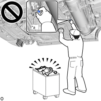 1.302,0.396 1.135,0.646 1.135,0.646 1.135,0.813 true 1.073,0.844 1.302,1 0.229,0.156 10 true *a
*a After depressurization procedures, the high pressure piping union nut that is loosened first.
After performing depressurization procedures, when first loosening the union nut of the high pressure hydrogen piping, do not loosen the union nut by hand without wearing protective glasses and gloves.
·Even when depressurization procedures are performed, the pressurized hydrogen gas inside the high pressure hydrogen piping cannot be completely depressurized, so the highly pressurized hydrogen gas remaining in the high pressure hydrogen piping could blow out, resulting in a serious accident.
·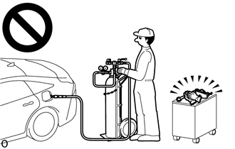
When performing the primary leak inspection, do not perform procedures without wearing protective glasses and gloves.
·High pressure nitrogen gas could cause a serious accident.
·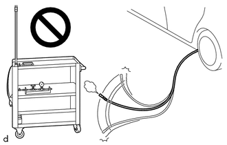
When opening the tank shut valve and applying pressure to SST (hydrogen venting tool), stay away from SST (flexible hose).
·If SST (flexible hose) comes off, you could be struck by the loose end of SST (flexible hose), causing a serious accident.
PROCEDURE

 1. PRECAUTION
- NOTICE:
- ·
After turning the ignition switch off, waiting time may be required before disconnecting the cable from the negative (-) auxiliary battery terminal.
Click hereGeneral>SETUP>WHEN DISCONNECTING OR RECONNECTING BATTERY TERMINAL>BEFORE DISCONNECTING BATTERY
·Place signs [HIGH PRESSURE GAS WORK IN PROGRESS - DO NOT TOUCH!], etc. to warn other technicians to be cautious. (An example sign is included, so make a copy and use it.)
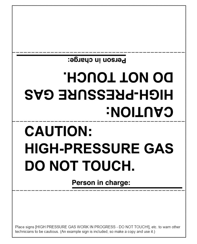 0.552,8.167 6.667,8.51 6.115,0.344 10 false Place signs [HIGH PRESSURE GAS WORK IN PROGRESS - DO NOT TOUCH!], etc. to warn other technicians to be cautious. (An example sign is included, so make a copy and use it.)
·When performing depressurization, do not open or close any parts of the hydrogen gas piping except for the following:
- Adjustment bolt of the hydrogen tank assembly manual valve
- Tank shut valve of the hydrogen tank assembly
- No. 1 hydrogen supply regulator plug
·When installing or removing the hydrogen tank assembly, high pressure hydrogen piping, hydrogen inlet receptacle, hydrogen tank tube joint assembly or hydrogen supply regulator, to prevent strain such as twisting from being applied to the high pressure hydrogen piping.
·Even when not removing or installing the high pressure hydrogen piping, be careful not to pull or otherwise apply strain to the high pressure hydrogen piping.
·When reusable parts such as the hydrogen tank assembly valve portion, hydrogen inlet receptacle, hydrogen tank tube joint assembly and hydrogen supply regulator have been removed, to protect the seal portions and threaded portions from damage as well as to prevent foreign matter such as dust and metal fragments from entering through openings, cover these areas with protective tape.
·Do not use packing tape, or any other tape that will leave residue on parts, as protective tape.
·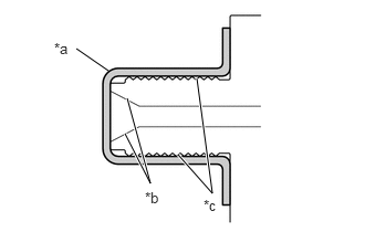 0.719,0.458 1.021,0.667 false 1.198,0.927 1.417,1.729 1.417,1.729 1.177,1.26 true 1.854,0.74 2,1.823 2,1.823 1.677,1.458 true 0.51,0.375 0.823,0.531 0.313,0.156 10 false *a 1.365,1.781 1.583,1.948 0.219,0.167 10 false *b 1.917,1.854 2.229,2.01 0.313,0.156 10 false *c
*a Protective Tape *b Seal Portion *c Threaded Portion
Protect seal portions and threaded portions as shown in the illustration.
·To protect the seal portions and threaded portions from damage or contamination by foreign matter, remove the protective tape immediately before installation.
·When reassembling components that have been removed, make sure that there is no foreign matter adhering to the openings.
·After installing high pressure hydrogen system components, first perform primary leak inspection with low pressure nitrogen gas, and then perform secondary leak inspection.
·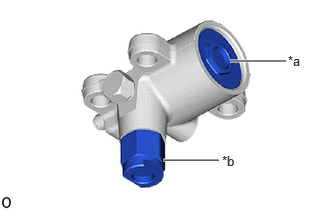 2.396,0.635 2.979,0.635 true 1.698,1.667 2.281,1.667 true 3,0.552 3.313,0.75 0.313,0.198 10 false *a 2.313,1.594 2.625,1.792 0.313,0.198 10 false *b
*a Atmosphere Ventilation Hole Cap *b Relief Valve
Do not insert any sharp objects into the relief valve of the hydrogen supply regulator.
·Do not remove the atmosphere ventilation hole cap of the hydrogen supply regulator.
·When the vehicle is parked with the ignition switch off, if the FC control ECU judges that the FC stack temperature will go below 0°C (32°F), it activates the FC air compressor, hydrogen pump and FC cooling water pump for a maximum of 180 seconds and drains water from the FC stack assembly. When performing inspection or repairs with the ignition switch off (not on (IG) or on (READY)), disconnect the cable from the negative (-) auxiliary battery terminal before performing work.
·When frost has formed on the hydrogen tank assembly or piping, water droplets may be formed when the frost begins to melt. If water droplets enter the tank or piping, it could result in blockage of the hydrogen piping, so do not allow water droplets to enter the tank or piping.
58404B
2.REMOVE REAR NO. 4 FLOOR BOARD SUB-ASSEMBLY
58403L
3.REMOVE REAR NO. 3 FLOOR BOARD SUB-ASSEMBLY
58402K
4.REMOVE NO. 2 FLOOR BOARD SUB-ASSEMBLY
|
|
Click here()
|
58401M
5.REMOVE NO. 1 FLOOR BOARD SUB-ASSEMBLY
|
|
Click here()
|
57628E
6.REMOVE REAR FLOOR SIDE MEMBER COVER LH
57627G
7.REMOVE REAR FLOOR SIDE MEMBER COVER RH
58398F
8.REMOVE NO. 1 FLOOR UNDER COVER
17DB3
9.REMOVE NO. 3 FC EXHAUST PIPE
10. PRESSURE RELEASE OPERATION
11.DISCONNECT CABLE FROM NEGATIVE AUXILIARY BATTERY TERMINAL
82161
12.DISCONNECT FLOOR WIRE
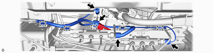
77BA2
13.DISCONNECT NO. 2 HYDROGEN TANK TUBE
|
|
|
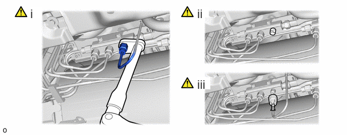
Using a 19 mm union nut wrench, loosen the union nut and disconnect the No. 2 hydrogen tank tube from the hydrogen tank tube joint assembly.
- NOTICE:
-
When frost has formed on the hydrogen tank assembly or piping, water droplets may be formed when the frost begins to melt. If water droplets enter the tank or piping, it could result in blockage of the hydrogen piping, so do not allow water droplets to enter the tank or piping.
To prevent contamination by foreign matter, cover the openings of the hydrogen tank tube joint assembly with protective tape.
- HINT:
-
When the hydrogen tank tube joint assembly will be replaced with a new one, it is not necessary to protect the openings with protective tape.
To prevent contamination by foreign matter, cover the connecting portions of the No. 2 hydrogen tank tube with plastic bags.
77BA4
14.DISCONNECT NO. 4 HYDROGEN TANK TUBE
|
|
|
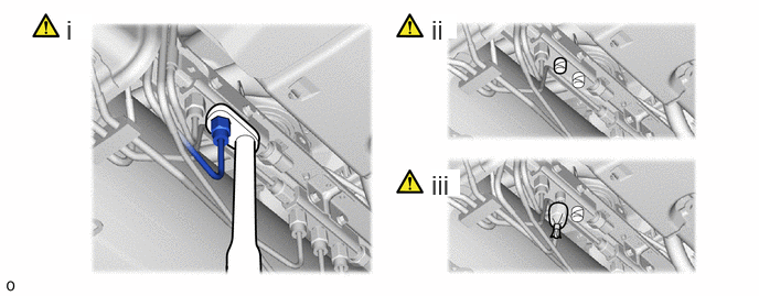
Using a 19 mm union nut wrench, loosen the union nut and disconnect the No. 4 hydrogen tank tube from the hydrogen tank tube joint assembly.
- NOTICE:
-
When frost has formed on the hydrogen tank assembly or piping, water droplets may be formed when the frost begins to melt. If water droplets enter the tank or piping, it could result in blockage of the hydrogen piping, so do not allow water droplets to enter the tank or piping.
To prevent contamination by foreign matter, cover the openings of the hydrogen tank tube joint assembly with protective tape.
- HINT:
-
When the hydrogen tank tube joint assembly will be replaced with a new one, it is not necessary to protect the openings with protective tape.
To prevent contamination by foreign matter, cover the connecting portions of the No. 4 hydrogen tank tube with plastic bags.
77BA1
15.DISCONNECT NO. 1 HYDROGEN TANK TUBE
|
|
|
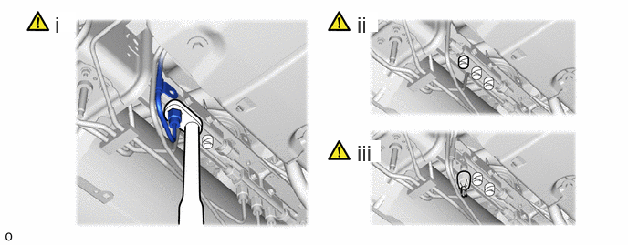
Using a 19 mm union nut wrench, loosen the union nut and disconnect the No. 1 hydrogen tank tube from the hydrogen tank tube joint assembly.
- NOTICE:
-
When frost has formed on the hydrogen tank assembly or piping, water droplets may be formed when the frost begins to melt. If water droplets enter the tank or piping, it could result in blockage of the hydrogen piping, so do not allow water droplets to enter the tank or piping.
To prevent contamination by foreign matter, cover the openings of the hydrogen tank tube joint assembly with protective tape.
- HINT:
-
When the hydrogen tank tube joint assembly will be replaced with a new one, it is not necessary to protect the openings with protective tape.
To prevent contamination by foreign matter, cover the connecting portions of the No. 1 hydrogen tank tube with plastic bags.
77BA3
16.DISCONNECT NO. 3 HYDROGEN TANK TUBE
|
|
|
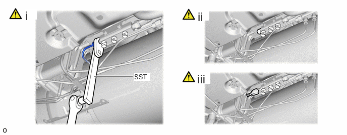
Using SST and a 19 mm union nut wrench, loosen the union nut and disconnect the No. 3 hydrogen tank tube from the hydrogen tank tube joint assembly.
- SST
- 09961-01270
- NOTICE:
-
When frost has formed on the hydrogen tank assembly or piping, water droplets may be formed when the frost begins to melt. If water droplets enter the tank or piping, it could result in blockage of the hydrogen piping, so do not allow water droplets to enter the tank or piping.
To prevent contamination by foreign matter, cover the openings of the hydrogen tank tube joint assembly with protective tape.
- HINT:
-
When the hydrogen tank tube joint assembly will be replaced with a new one, it is not necessary to protect the openings with protective tape.
To prevent contamination by foreign matter, cover the connecting portions of the No. 3 hydrogen tank tube with plastic bags.
77BC0
17.REMOVE HYDROGEN TANK TUBE JOINT ASSEMBLY
|
|
|