FC CONTROL FC CONTROL SYSTEM P1DDF79 FC Air Flow Mechanical Linkage Failure
DESCRIPTION
| DTC No. | Detection Item | DTC Detection Condition | Trouble Area | Warning Indicate | DTC Output from | Priority |
|---|---|---|---|---|---|---|
| P1DDF79 | FC Air Flow Mechanical Linkage Failure | The value of the intercooler outlet pressure sensor (vacuum sensor) is lower than the intercooler outlet pressure calculated and estimated by the mass air flow meter sub-assembly and atmospheric pressure sensor (EV control ECU)
(1 trip detection logic) |
·
Air leak in air pipes ·
Mass air flow meter sub-assembly ·
Barometric pressure sensor (EV control ECU) ·
FC stack inlet air pressure sensor (vacuum sensor assembly) |
Master Warning: Comes on | EV | B |
| Vehicle Condition | FC shutdown
(ignition switch ON) |
FC startup process | FC intermittent operation | FC is generating power
(vehicle is in stationary) |
FC is generating power
(vehicle is traveling) |
FC shutdown process |
|---|---|---|---|---|---|---|
| Data List
"FC Work Mode" |
Stop | Startup | Working | Finishing | ||
| Data List
"FC Intermittent Operation" |
OFF | ON | OFF | OFF | ||
| DTC Detection | - | - | - | ○ | ○ | - |
- HINT:
-
By accessing the "FC Work Mode" and "FC Intermittent Operation" in the freeze frame data, the FC system condition at the time the malfunction occurred can be checked.
| DTC No. | Data List |
|---|---|
| P1DDF79 | ·
Mass Air Flow (Filtered Value) ·
FC Inter Cooler Outlet Pressure ·
Atmospheric Pressure |
WIRING DIAGRAM
Refer to DTC P010031.
Click hereEngine / Hybrid System>FC CONTROL>FC CONTROL SYSTEM>P010031
Refer to DTC P1D9011.
Click hereEngine / Hybrid System>FC CONTROL>FC CONTROL SYSTEM>P1D9011
CAUTION / NOTICE / HINT
- NOTICE:
- ·
This vehicle performs FC system shutdown process after turning the ignition switch off from ON (READY). Therefore, after the ignition switch is turned off from ON (READY), do not perform any work on the electrical system for at least 10 minutes including removing connectors or disconnecting the negative (-) auxiliary battery terminal.
·When the EV control ECU determines that the temperature of FC system components is below 0°C (32°F) when the vehicle is parked with the ignition switch off, it operates the FC air compressor, hydrogen pump and FC cooling water pump for a maximum of 180 seconds to drain the FC stack assembly. When performing inspection or repairs with the ignition switch off (not ON or ON (READY)), disconnect the cable from the negative (-) auxiliary battery terminal before performing work. (If the auxiliary battery voltage is needed to conduct inspection, perform the inspection in an environment with an ambient temperature of 10°C (50°F) or higher.)
- HINT:
-
After the repair, clear the DTCs and perform the following procedure to check that DTCs are not output.
- 1.
Drive the vehicle at 70 km/h or higher for approximately 15 seconds (Vehicle has to run continuously at the speed).
- CAUTION:
-
Perform this road test only in an appropriate safe location, in accordance with all local laws.
PROCEDURE
- NOTICE:
-
The freeze frame data is cleared when DTCs are cleared. Be sure to make a note of necessary data in advance.
Pre-procedure1
Drive the vehicle at a speed of approximately 40 to 60 km/h (25 to 37 mph) for at least 5 minutes (Vehicle does not have to run continuously at the speeds).
- CAUTION:
-
Perform this road test only in an appropriate safe location, in accordance with all local laws.
Procedure1
According to the display on the GTS, check for DTCs in the Health Check.
- Result:
Result Proceed to Only P1DDF76 is output A P1DDF76 is output and DTCs other than the DTCs in the table below are output B P1DDF79 is output and any DTCs in the table below are output C
Malfunction Content Relevant DTC Sensor and actuator circuit malfunction P010031 (EV) Mass or Volume Air Flow Sensor "A" No Signal P1D9011 (EV) FC Stack Inlet Pressure Sensor Circuit Short to Ground P1D9015 (EV) FC Stack Inlet Pressure Sensor Circuit Short to Battery or Open P222612 (Hybrid (EV) Control System) Barometric Pressure Sensor "A" Circuit Short to Battery P222614 (Hybrid (EV) Control System) Barometric Pressure Sensor "A" Circuit Short to Ground or Open P222A12 (EV) Barometric Pressure Sensor "B" Circuit Short to Battery P222A14 (EV) Barometric Pressure Sensor "B" Circuit Short to Ground or Open
- HINT:
-
DTC P1DDF79 may be store due to problems that cause the DTCs shown above to be output. If such happens, troubleshoot the suspected area(s) corresponding to the output DTC(s) in order of the listed DTCs shown in the table above.
Post-procedure1
Turn the ignition switch off.
A
B
C
Hybrid (EV) Control System:
Click hereEngine / Hybrid System>HYBRID / BATTERY CONTROL>HYBRID CONTROL SYSTEM>DIAGNOSIS SYSTEM
Check that no air comes in without flowing through each part of the intake air system and the exhaust drainage pipe is not clogged, disconnected, or damaged.
- HINT:
-
Check the area extending from the FC air compressor assembly with motor to the FC air pressure regulator assembly (air shunt valve) downstream piping.
- OK:
The intake and exhaust piping is not clogged, disconnected or damaged
- Result:
Proceed to OK NG
OK
NG
Pre-procedure1
None
Procedure1
Read the value displayed on the GTS.
- Powertrain > EV > Data List
-
Tester Display Atmospheric Pressure FC Inter Cooler Outlet Pressure - 50003 397 888,1037
Using the table, read the normal atmospheric pressure value for the applicable altitude.
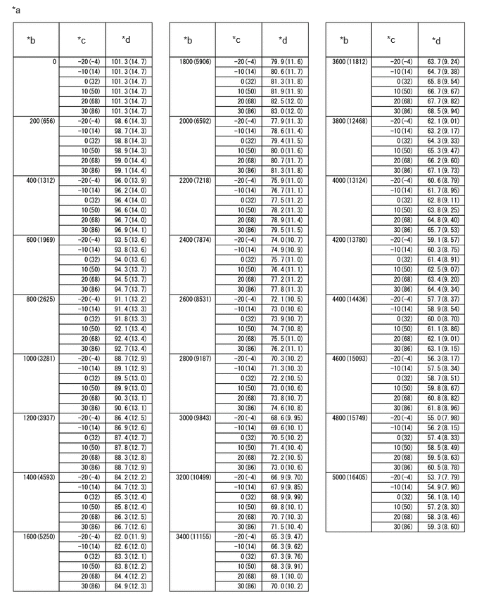
| *a | Altitude, Temperature and Atmospheric Pressure Correlation Table | *b | Altitude (m (ft.)) |
| *c | Temperature (°C (°F)) | *d | Atmospheric Pressure (kPa (psi)) |
- HINT:
- ·
Standard atmospheric pressure is approximately 101 kPa (15 psi).
·For every 100 m (328 ft.) increase in altitude, atmospheric pressure drops by approximately 1 kPa (0.1 psi). This varies by weather.
Compare the "FC Inter Cooler Outlet Pressure" and "Atmospheric Pressure" values in the Data List with the normal atmospheric value.
- Result:
Result Proceed to Difference between "FC Inter Cooler Outlet Pressure" in Data List and normal atmospheric pressure value is 10 kPa or more. A Difference between "Atmospheric Pressure" in Data List and normal atmospheric pressure value is 10 kPa or more. B Other than above. C
Post-procedure1
Turn the ignition switch off.
A
B
C
Pre-procedure1
Turn the ignition switch to ON.
Procedure1
Read the value displayed on the GTS.
- Powertrain > EV > Data List
-
Tester Display Mass Air Flow (Filtered Value) - 50003 397 897
- Result:
Result Proceed to The value of Mass Air Flow (Filtered Value) is less than 8 L/min A None of the above conditions are met B
- HINT:
- ·
If "Mass Air Flow (Filtered Value)" is outside of the standard value when the ignition switch is ON, it can be determined that there is a deviation in output with no air blowing
·A "Mass Air Flow (Filtered Value)" deviation cannot be determined while the FC air compressor is operating under a high load, so replace the mass air flow meter sub-assembly even if the result is normal with no air blowing.
Post-procedure1
Turn the ignition switch off.
A
B
- HINT:
-
Click hereEngine / Hybrid System>FC CONTROL>INTAKE AIR FLOW METER>REMOVAL
- Result:
Proceed to NEXT
NEXT
Pre-procedure1
Drive the vehicle for 10 minutes according to the freeze frame data (Vehicle Speed, Accelerator Degree, etc.)
- CAUTION:
-
Perform this road test only in an appropriate safe location, in accordance with all local laws.
- HINT:
-
If vehicle speeds, accelerator pedal positions, road conditions, ambient temperatures and climates at the time the malfunction occurred can be found out, take them into account.
Procedure1
Check for DTCs.
- Powertrain > EV > Trouble Codes
- 50001 397
- Result:
Result Proceed to DTCs are not output A P1DDF79 is output B
Post-procedure1
Turn the ignition switch off.
A
Click hereGeneral>INTRODUCTION>HOW TO TROUBLESHOOT ECU CONTROLLED SYSTEMS>HOW TO PROCEED WITH TROUBLESHOOTING
B