INTAKE / EXHAUST AIR COMPRESSOR REMOVAL
CAUTION / NOTICE / HINT
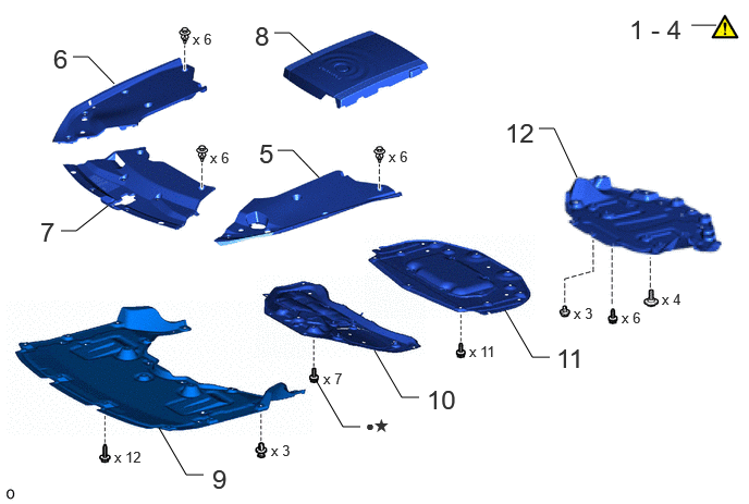
| Procedure | Part Name Code | 
|

|

|
|
|---|---|---|---|---|---|
| 1 | CAUTIONS FOR HIGH VOLTAGE SYSTEM COMPONENTS | - | ( ) |
- | - |
| 2 | CAUTIONS FOR COOLANT (TOYOTA GENUINE FC STACK COOLANT (Pre-mixed)) | - | ()
|
- | - |
| 3 | CAUTIONS FOR INTAKE SYSTEM COMPONENTS | - | ()
|
- | - |
| 4 | PRECAUTION | - | ()
|
- | - |
| 5 | UPPER RADIATOR SUPPORT SEAL | 53292A | - | - | - |
| 6 | RADIATOR COVER PLATE | 53291B | - | - | - |
| 7 | LOWER RADIATOR AIR DEFLECTOR | 53295 | - | - | - |
| 8 | FC STACK COVER SUB-ASSEMBLY | 1A906 | - | - | - |
| 9 | FRONT COMPARTMENT UNDER COVER | 51441N | - | - | - |
| 10 | FRONT LOWER SUSPENSION MEMBER PROTECTOR | 51219 | - | - | - |
| 11 | FRONT COMPARTMENT UNDER COVER ASSEMBLY | 51420A | - | - | - |
| 12 | REAR NO. 4 FLOOR BOARD SUB-ASSEMBLY | 58404B | - | - | - |
| ● | Non-reusable part | ★ | Precoated part |
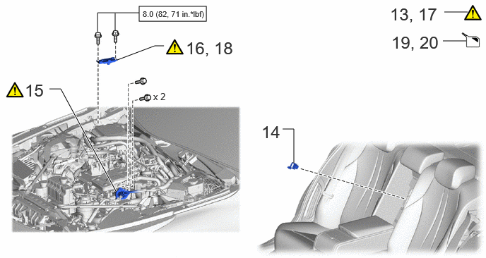
| Procedure | Part Name Code |
|
|
|
|
|---|---|---|---|---|---|
| 13 | PRECAUTION | - | ()
|
- | - |
| 14 | SERVICE PLUG GRIP | G3834 | - | - | - |
| 15 | FC CONVERTER POWER OUTLET CABLE (INVERTER WITH CONVERTER ASSEMBLY) | G9200A | ()
|
- | - |
| 16 | REMOVE CONNECTOR COVER ASSEMBLY | - | ()
|
- | - |
| 17 | CHECK TERMINAL VOLTAGE | - | ()
|
- | - |
| 18 | INSTALL CONNECTOR COVER ASSEMBLY | - | ()
|
- | - |
| 19 | DRAIN COOLANT (TOYOTA GENUINE FC STACK COOLANT (Pre-mixed)) | - | - | ()
|
- |
| 20 | DRAIN COOLANT (for Inverter) | - | - | ()
|
- |

|
N*m (kgf*cm, ft.*lbf): Specified torque | - | - |
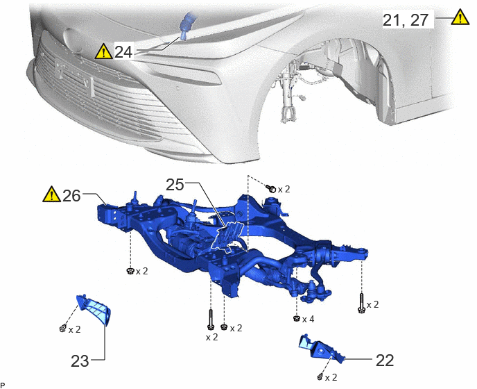
| Procedure | Part Name Code |
|
|
|
|
|---|---|---|---|---|---|
| 21 | ENGINE SUPPORT BRIDGE | - | - | - | - |
| 22 | FRONT COMPARTMENT SIDE COVER LH | 51474C | - | - | - |
| 23 | FRONT COMPARTMENT SIDE COVER RH | 51473D | - | - | - |
| 24 | NO. 2 STEERING INTERMEDIATE SHAFT ASSEMBLY | 45260 | ()
|
- | - |
| 25 | WIRE HARNESS CLAMP BRACKET | - | - | - | - |
| 26 | FRONT FRAME ASSEMBLY | 51100G | ()
|
- | - |
| 27 | HOLDING BAR | - | ()
|
- | - |
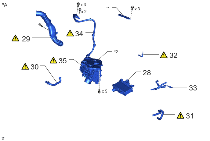
| Procedure | Part Name Code |
|
|
|
|
|---|---|---|---|---|---|
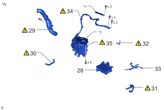
| 28 | INTERCOOLER WITH SENSOR ASSEMBLY | 17900 | - | - | - |
| 29 | AIR CLEANER HOSE ASSEMBLY | 17880D | ()
|
- | - |
| 30 | NO. 15 FC INVERTER COOLING HOSE | G91CF | ()
|
- | - |
| 31 | NO. 13 FC INVERTER COOLING HOSE | G91CD | ()
|
- | - |
| 32 | NO. 1 AIR COMPRESSOR BREATHER HOSE | 17A40 | ()
|
- | - |
| 33 | WIRE HARNESS | - | - | - | - |
| 34 | FC AIR COMPRESSOR MOTOR CABLE ASSEMBLY | 17A90 | ()
|
- | - |
| 35 | FC AIR COMPRESSOR WITH MOTOR ASSEMBLY | 17A10 | ()
|
- | - |
| *A | for LHD | - | - |
| *1 | INVERTER TERMINAL COVER | *2 | FC AIR COMPRESSOR BRACKET |
| Procedure | Part Name Code |
|
|
|
|
|---|---|---|---|---|---|
| 28 | INTERCOOLER WITH SENSOR ASSEMBLY | 17900 | - | - | - |
| 29 | AIR CLEANER HOSE ASSEMBLY | 17880D | ()
|
- | - |
| 30 | NO. 15 FC INVERTER COOLING HOSE | G91CF | ()
|
- | - |
| 31 | NO. 13 FC INVERTER COOLING HOSE | G91CD | ()
|
- | - |
| 32 | NO. 1 AIR COMPRESSOR BREATHER HOSE | 17A40 | ()
|
- | - |
| 33 | WIRE HARNESS | - | - | - | - |
| 34 | FC AIR COMPRESSOR MOTOR CABLE ASSEMBLY | 17A90 | ()
|
- | - |
| 35 | FC AIR COMPRESSOR WITH MOTOR ASSEMBLY | 17A10 | ()
|
- | - |
| *A | for RHD | - | - |
| *1 | INVERTER TERMINAL COVER | *2 | FC AIR COMPRESSOR BRACKET |
CAUTION / NOTICE / HINT
The necessary procedures (adjustment, calibration, initialization, or registration) that must be performed after parts are removed, installed, or replaced during the FC air compressor with motor assembly removal/installation are shown below.
| Replacement Part or Procedure | Necessary Procedure | Effects/Inoperative when not Performed | Link |
|---|---|---|---|
|
*: The vehicle height changes because of suspension or tire replacement. |
|||
| Disconnect cable from negative auxiliary battery terminal | Memorize steering angle neutral point | Parking assist monitor system | ()
|
| Panoramic view monitor system | ()
|
||
| Suspension, tires, etc.* | ·
Measurement of ultrasonic sensor detection angle ·
Ultrasonic sensor detection angle registration |
·
Parking support brake system ·
Advanced park |
w/ Advanced Park:
( )
w/o Advanced Park: ( )
|
| Rear television camera assembly optical axis (Back camera position setting) | Parking assist monitor system | ()
|
|
·
Parking assist ECU initialization ·
Adjust steering angle ·
Rear television camera view adjustment (for Rear camera detection system) |
Panoramic view monitor system | ()
|
|
| Perform headlight ECU sub-assembly LH initialization | Automatic headlight beam level control system | ()
|
|
| Front bumper assembly (Including removal and installation) | ·
Measurement of ultrasonic sensor detection angle ·
Ultrasonic sensor detection angle registration |
·
TOYOTA Parking assist- sensor system ·
Parking support brake system ·
Advanced park |
w/ Advanced Park:
( )
w/o Advanced Park: ( )
|
| Front television camera view adjustment | Panoramic view monitor system | ()
|
|
| Wheel alignment adjustment | Perform "Calibration" | Electronically controlled brake system malfunctions | ()
|
- HINT:
-
When the cable is disconnected/reconnected to the auxiliary battery terminal, systems temporarily stop operating. However, each system has a function that completes learning the first time the system is used.
- ·
Learning completes when vehicle is driven
Effect/Inoperative Function When Necessary Procedures are not Performed Necessary Procedures Link Lane tracing assist system Drive the vehicle straight ahead at 35 km/h (22 mph) or more for 5 seconds or more. ( )
Pre-collision system Adaptive high beam system
·Learning completes when vehicle is operated normally
Effect/Inoperative Function When Necessary Procedures are not Performed Necessary Procedures Link Air conditioning system After the ignition switch is turned to ON, the servo motor and expansion valve standard position is recognized. -
- CAUTION:
- ·
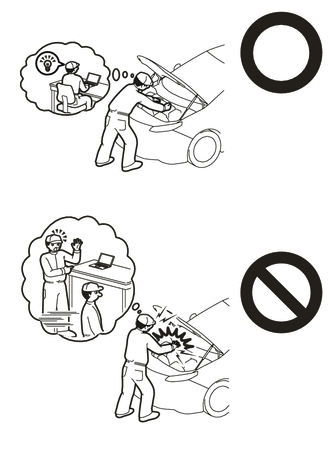
This vehicle has contains high voltage circuits standardized with orange colored wiring and connectors, so follow the instructions in this manual to perform the procedures correctly.
Click hereEngine / Hybrid System>HYBRID / BATTERY CONTROL>HYBRID BATTERY SYSTEM>PRECAUTION
·If the correct procedures are not followed according to the instructions in this manual, there is a danger of electric shock from the high voltage circuits.
- ·
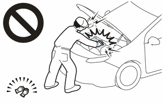
Be sure to wear insulating gloves when working on high voltage wiring or components.
·If work is performed without wearing insulating gloves, there is a danger of electric shock.
- ·
 2.573,0.583 2.906,0.583 false 2.948,0.479 3.26,0.677 0.313,0.198 10 false *a
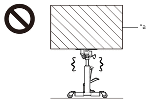
*a Heavy object exceeding the capacity of the transmission jack
Because the weight of the FC air compressor with motor assembly is extremely heavy, make sure to follow the work procedures described in the repair manual.
·If work is not performed according to the procedures described in the repair manual, there is a danger that the transmission jack could drop and components could fall down.
·Be sure to perform this procedure with several people as the transfer assembly is very heavy.
- NOTICE:
-
When the vehicle is parked with the power switch off, if the FC control ECU judges that the FC stack temperature will go below 0°C (32°F), it activates the FC air compressor, hydrogen pump and FC cooling water pump for a maximum of 180 seconds and drains water from the FC stack assembly. When performing inspection or repairs with the power switch off (not on (IG) or on (READY)), disconnect the cable from the negative (-) auxiliary battery terminal before performing work.
PROCEDURE

 1. CAUTIONS FOR HIGH VOLTAGE SYSTEM COMPONENTS
|
|
Click here()
|
2. CAUTIONS FOR COOLANT (TOYOTA GENUINE FC STACK COOLANT (Pre-mixed))
3. CAUTIONS FOR INTAKE SYSTEM COMPONENTS
|
|
|
4. PRECAUTION
- NOTICE:
-
After turning the power switch off, waiting time may be required before disconnecting the cable from the negative (-) auxiliary battery terminal.
-
Click hereGeneral>SETUP>WHEN DISCONNECTING OR RECONNECTING BATTERY TERMINAL>BEFORE DISCONNECTING BATTERY
53292A
5.REMOVE UPPER RADIATOR SUPPORT SEAL
53291B
6.REMOVE RADIATOR COVER PLATE
53295
7.REMOVE LOWER RADIATOR AIR DEFLECTOR
1A906
8.REMOVE FC STACK COVER SUB-ASSEMBLY
51441N
9.REMOVE FRONT COMPARTMENT UNDER COVER
51219
10.REMOVE FRONT LOWER SUSPENSION MEMBER PROTECTOR
51420A
11.REMOVE FRONT COMPARTMENT UNDER COVER ASSEMBLY
58404B
12.REMOVE REAR NO. 4 FLOOR BOARD SUB-ASSEMBLY
13. PRECAUTION
|
|
Click here()
|
G3834
14.REMOVE SERVICE PLUG GRIP
G9200A
15.DISCONNECT FC CONVERTER POWER OUTLET CABLE (INVERTER WITH CONVERTER ASSEMBLY)
|
|
Click here()
|
16.REMOVE CONNECTOR COVER ASSEMBLY
|
|
Click here()
|
17.CHECK TERMINAL VOLTAGE
|
|
Click here()
|
18.INSTALL CONNECTOR COVER ASSEMBLY
|
|
Click here()
|
19.DRAIN COOLANT (TOYOTA GENUINE FC STACK COOLANT (Pre-mixed))
20.DRAIN COOLANT (for Inverter)
21.INSTALL ENGINE SUPPORT BRIDGE
51474C
22.REMOVE FRONT COMPARTMENT SIDE COVER LH
51473D
23.REMOVE FRONT COMPARTMENT SIDE COVER RH
Use the same procedure as for the LH side.
45260
24.DISCONNECT NO. 2 STEERING INTERMEDIATE SHAFT ASSEMBLY
|
|
Click here()
|
25.DISCONNECT WIRE HARNESS CLAMP BRACKET
51100G
26.REMOVE FRONT FRAME ASSEMBLY
|
|
Click here()
|
27.INSTALL HOLDING BAR
|
|
Click here()
|
17900
28.REMOVE INTERCOOLER WITH SENSOR ASSEMBLY
17880D
29.REMOVE AIR CLEANER HOSE ASSEMBLY
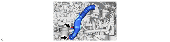
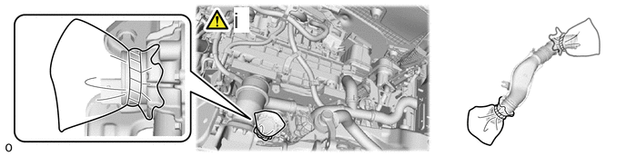
To prevent contamination by foreign matter or water droplets, cover the connecting portions of the air cleaner hose assembly and FC air compressor with motor assembly with plastic bags.
G91CF
30.DISCONNECT NO. 15 FC INVERTER COOLING HOSE
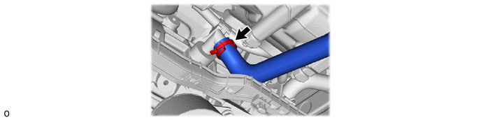
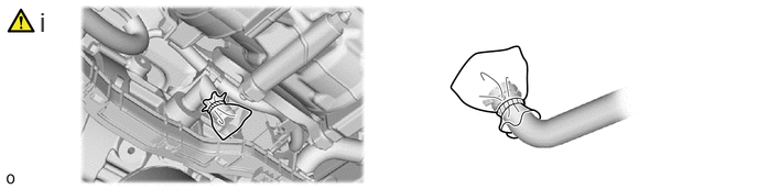
To prevent contamination by foreign matter or water droplets, cover the connecting portions of the No. 15 FC inverter cooling hose and FC air compressor with motor assembly with plastic bags.
G91CD
31.DISCONNECT NO. 13 FC INVERTER COOLING HOSE
|
|
Click here()
|
17A40
32.DISCONNECT NO. 1 AIR COMPRESSOR BREATHER HOSE
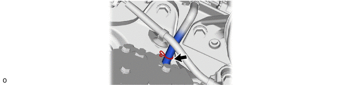
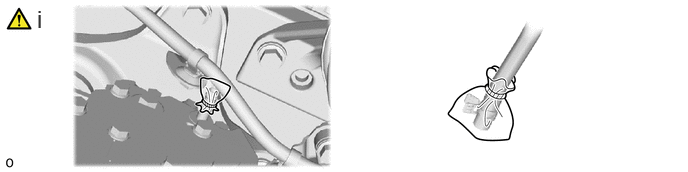
To prevent contamination by foreign matter or water droplets, cover the connecting portions of the FC air compressor breather hose and FC air compressor with motor assembly with plastic bags.
33.DISCONNECT WIRE HARNESS
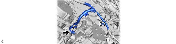
17A90
34.DISCONNECT FC AIR COMPRESSOR MOTOR CABLE ASSEMBLY
|
|
|
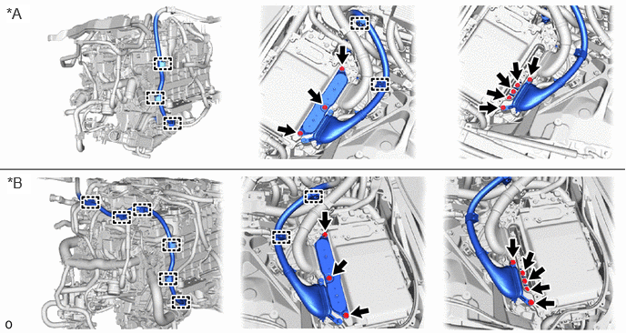
| *A | for LHD | *B | for RHD |
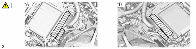
| *A | for LHD | *B | for RHD |
To prevent contamination by foreign matter or water droplets, cover the opening of the inverter with converter assembly with protective tape.
17A10
35.REMOVE FC AIR COMPRESSOR WITH MOTOR ASSEMBLY
|
|
|
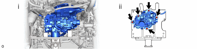
Support the FC air compressor with motor assembly with a transmission jack.
Remove the 5 bolts, FC air compressor with motor assembly and FC air compressor bracket from the fc stack frame assembly.