Q710 HYBRID TRANSMISSION / TRANSAXLE HYBRID VEHICLE TRANSAXLE INSTALLATION
CAUTION / NOTICE / HINT
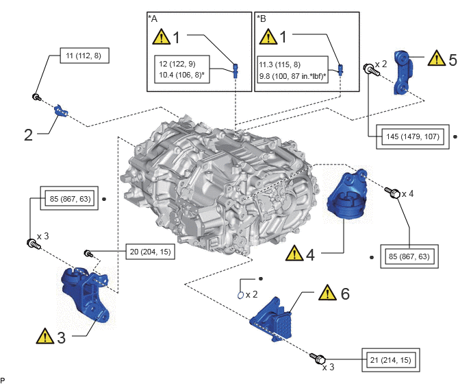
| Procedure | Part Name Code | 
|

|

|
|
|---|---|---|---|---|---|
| 1 | TRANSAXLE BREATHER PLUG | 30900N | ( ) |
- | - |
| 2 | MOTOR CABLE BRACKET | G1143 | - | - | - |
| 3 | MOTOR MOUNTING INSULATOR SUB-ASSEMBLY RH | G2305A | ()
|
- | - |
| 4 | MOTOR MOUNTING INSULATOR LH | G2372 | ()
|
- | - |
| 5 | REAR MOTOR MOUNTING BRACKET | G2321A | ()
|
- | - |
| 6 | OIL WITH MOTOR PUMP ASSEMBLY | 35300 | ()
|
- | - |
| *A | for Type A | *B | for Type B |

|
Tightening torque for "Major areas involving basic vehicle performance such as moving/turning/stopping": N*m (kgf*cm, ft.*lbf) | 
|
N*m (kgf*cm, ft.*lbf): Specified torque |
| * | For use with union nut wrench | ● | Non-reusable part |
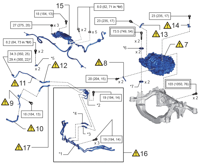
| Procedure | Part Name Code |
|
|
|
|
|---|---|---|---|---|---|
| 7 | FCV WITH MOTOR TRANSAXLE ASSEMBLY | 30600R | ()
|
- | - |
| 8 | MOTOR MOUNTING STAY LH | G2318 | ()
|
- | - |
| 9 | OIL COOLER INLET TUBE SUB-ASSEMBLY | 32904B | ()
|
- | - |
| 10 | NO. 1 OIL COOLER INLET HOSE | 32941L | ()
|
- | - |
| 11 | OIL COOLER OUTLET TUBE SUB-ASSEMBLY | 32905B | ()
|
- | - |
| 12 | NO. 1 OIL COOLER OUTLET HOSE | 32942G | ()
|
- | - |
| 13 | NO. 4 CABLE SUPPORT BRACKET | 46454A | ()
|
- | - |
| 14 | NO. 3 CABLE SUPPORT BRACKET | 46453A | ()
|
- | - |
| 15 | PARKING BRAKE ACTUATOR ASSEMBLY WITH BRACKET | 46300 | - | - | - |
| 16 | OIL COOLER TUBE ASSEMBLY | - | ()
|
- | - |
| 17 | NO. 2 OIL COOLER INLET HOSE | 32941M | ()
|
- | - |
| *1 | OIL COOLER TUBE SUB-ASSEMBLY | *2 | OIL COOLER WITHOUT HOSE TUBE SUB-ASSEMBLY |
| *3 | NO. 2 OIL COOLER INLET HOSE | *4 | NO. 2 OIL COOLER OUTLET HOSE |
| *5 | NO. 2 OIL COOLER TUBE CLAMP | *6 | UPPER MOTOR MOUNTING STOPPER |
| *7 | LOWER MOTOR MOUNTING STOPPER | - | - |
|
|
Tightening torque for "Major areas involving basic vehicle performance such as moving/turning/stopping": N*m (kgf*cm, ft.*lbf) |
|
N*m (kgf*cm, ft.*lbf): Specified torque |
| * | For use with union nut wrench | - | - |
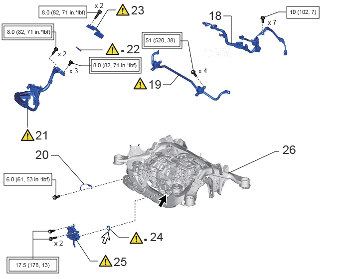
| Procedure | Part Name Code |
|
|
|
|
|---|---|---|---|---|---|
| 18 | WIRE HARNESS | - | - | - | - |
| 19 | REAR STABILIZER BAR | 48812 | ()
|
- | - |
| 20 | NO. 1 BOND CABLE | 82001 | - | - | - |
| 21 | MOTOR CABLE | G1148 | ()
|
- | - |
| 22 | MOTOR CABLE TERMINAL CAP | G114D | ()
|
- | - |
| 23 | CONNECTOR COVER | 82821T | ()
|
- | - |
| 24 | SHIFT CONTROL ACTUATOR SEAL | 35563 | ()
|
- | - |
| 25 | SHIFT CONTROL ACTUATOR ASSEMBLY | 35580 | ()
|
- | - |
| 26 | REAR SUSPENSION MEMBER SUB-ASSEMBLY | 51206A | - | - | - |
|
|
Tightening torque for "Major areas involving basic vehicle performance such as moving/turning/stopping": N*m (kgf*cm, ft.*lbf) |
|
N*m (kgf*cm, ft.*lbf): Specified torque |
| ● | Non-reusable part | 
|
Toyota Genuine ATF WS |

|
MP grease | - | - |
PROCEDURE

 30900N
1.INSTALL TRANSAXLE BREATHER PLUG
|
|
|
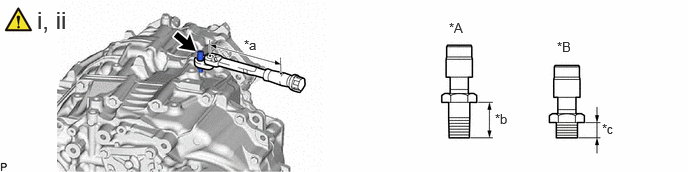
| *A | for Type A | *B | for Type B |
| *a | Torque Wrench Fulcrum Length | *b | 16.5 mm (0.650 in.) |
| *c | 9.5 mm (0.374 in.) | - | - |
for Type A:
Using a 14 mm union nut wrench, install the transaxle breather plug to the FCV with motor transaxle assembly.
- Torque:
- Specified Tightening Torque : 12 N*m (122 kgf*cm, 9 ft.*lbf)
- HINT:
- ·
Calculate the torque wrench reading when changing the fulcrum length of the torque wrench.
Click hereGeneral>INTRODUCTION>REPAIR INSTRUCTION>PRECAUTION
·When using a 14 mm union nut wrench (fulcrum length of 25 mm (0.984 in.)) + torque wrench (fulcrum length of 162 mm (6.38 in.): 10.4 N*m (106 kgf*cm, 8 ft.*lbf)
for Type B:
Using a 14 mm union nut wrench, install the transaxle breather plug to the FCV with motor transaxle assembly.
- Torque:
- Specified Tightening Torque : 11.3 N*m (115 kgf*cm, 8 ft.*lbf)
- HINT:
- ·
Calculate the torque wrench reading when changing the fulcrum length of the torque wrench.
Click hereGeneral>INTRODUCTION>REPAIR INSTRUCTION>PRECAUTION
·When using a 14 mm union nut wrench (fulcrum length of 25 mm (0.984 in.)) + torque wrench (fulcrum length of 162 mm (6.38 in.): 9.8 N*m (100 kgf*cm, 87 in.*lbf)
G1143
2.INSTALL MOTOR CABLE BRACKET
- Torque:
- 11 N*m (112 kgf*cm, 8 ft.*lbf)
G2305A
3.INSTALL MOTOR MOUNTING INSULATOR SUB-ASSEMBLY RH

|
|
Bolt A |
|
Bolt B |
Install the motor mounting insulator sub-assembly RH to the FCV with motor transaxle assembly with the 3 new bolts A and bolt B.
- Torque:
- for bolt A : 85 N*m (867 kgf*cm, 63 ft.*lbf)
- for bolt B : 20 N*m (204 kgf*cm, 15 ft.*lbf)
- HINT:
-
Tightening order: Temporarily install bolt A and bolt B → Tighten bolt A → Tighten bolt B
G2372
4.INSTALL MOTOR MOUNTING INSULATOR LH

|
|
Bolt A |
|
Bolt B |

|
Bolt C | 
|
Bolt D |
Install the motor mounting insulator LH to the FCV with motor transaxle assembly with the 4 new bolts.
- Torque:
- : 85 N*m (867 kgf*cm, 63 ft.*lbf)
- HINT:
-
Tightening order: Temporarily install bolt A → Tighten bolt B → Tighten bolt A, bolt C and bolt D
G2321A
5.INSTALL REAR MOTOR MOUNTING BRACKET

|
|
Bolt A |
|
Bolt B |
Install the rear motor mounting bracket to the FCV with motor transaxle assembly with the 2 new bolts.
- Torque:
- 145 N*m (1479 kgf*cm, 107 ft.*lbf)
- HINT:
-
Tightening order: Temporarily install bolt A → Tighten bolt B → Tighten bolt A
35300
6.INSTALL OIL WITH MOTOR PUMP ASSEMBLY
|
|
Click here()
|
30600R
7.INSTALL FCV WITH MOTOR TRANSAXLE ASSEMBLY
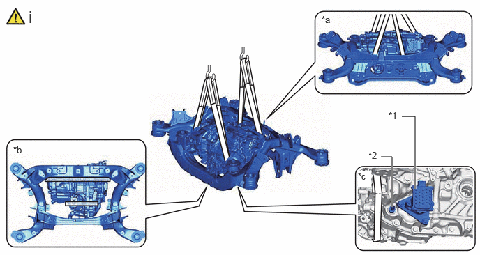
| *1 | Oil with Motor Pump Assembly | *2 | Connector Tube |
| *a | Rear Side of Vehicle | *b | Bottom Side of Vehicle |
| *c | LH Side of Vehicle | - | - |
Using an engine sling device, chain block and rope or equivalent, hold the FCV with motor transaxle assembly.
- CAUTION:
-
The FCV with motor transaxle assembly is heavy. Hold it securely in place with engine sling device, chain block and belt sling.
- NOTICE:
- ·
Do not drop the FCV with motor transaxle assembly.
·Do not damage the installation surface of the FCV with motor transaxle assembly.
·Lightly shake the FCV with motor transaxle assembly by hand to make sure it is securely held while performing work.
·Do not shake the FCV with motor transaxle assembly excessively while holding it.
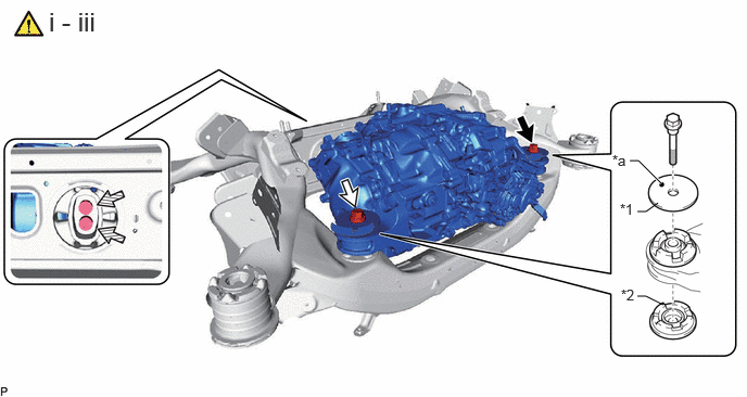
| *1 | Upper Motor Mounting Stopper | *2 | Lower Motor Mounting Stopper |
| *a | Paint Mark of Upper Motor Mounting Stopper | - | - |
|
|
Bolt A |
|
Bolt B |
|
|
Bolt C | - | - |
Temporarily install the 2 upper motor mounting stoppers, the 2 lower motor mounting stoppers and the FCV with motor transaxle assembly to the rear suspension member sub-assembly with the 4 bolts as shown in the illustration.
- NOTICE:
-
Install so that the identification paint marks of the upper motor mounting stoppers face upward and the rubber stopper sides of the lower motor mounting stoppers face upward as shown in the illustration.
Tighten the 4 bolts in the tightening order.
- Torque:
- for bolt A and bolt B : 73.5 N*m (749 kgf*cm, 54 ft.*lbf)
- for bolt C : 103 N*m (1050 kgf*cm, 76 ft.*lbf)
- HINT:
-
Tightening order: Temporarily install bolt A → Temporarily install bolt B → Temporarily install bolt C → Tighten bolt C → Tighten bolt A → Tighten bolt B
Remove the engine sling device, chain block and rope or equivalent.
G2318
8.INSTALL MOTOR MOUNTING STAY LH

|
|
Bolt A |
|
Bolt B |
Install the motor mounting stay LH to the FCV with motor transaxle assembly with the 2 bolts.
- Torque:
- 20 N*m (204 kgf*cm, 15 ft.*lbf)
- HINT:
-
Tightening order: Temporarily install bolt A → Tighten bolt B → Tighten bolt A
32904B
9.INSTALL OIL COOLER INLET TUBE SUB-ASSEMBLY
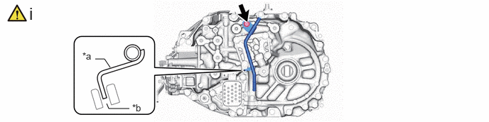
| *a | Oil Cooler Inlet Tube Sub-assembly Stopper | *b | Transmission Oil Pump Cover Sub-assembly Hole |
Install the oil cooler inlet tube sub-assembly to the FCV with motor transaxle assembly with the bolt as shown in the illustration.
- Torque:
- 18 N*m (184 kgf*cm, 13 ft.*lbf)
- NOTICE:
-
Insert the oil cooler inlet tube sub-assembly stopper into the transmission oil pump cover sub-assembly hole.
32941L
10.INSTALL NO. 1 OIL COOLER INLET HOSE
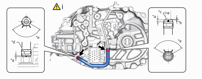
| *a | 2 to 7 mm (0.0787 to 0.275 in.) | *b | 0 to 3 mm (0 to 0.118 in.) |
| *c | Paint Mark (LH Side of Vehicle) | *d | Paint Mark (Lower Side of Vehicle) |
| *e | 120° (Claw of Hose Clip Location) | - | - |
Install the No. 1 oil cooler inlet hose to the oil cooler inlet tube sub-assembly and FCV with motor transaxle assembly, and slide the 2 hose clips to secure the hose.
- NOTICE:
- ·
Make sure to slide the No. 1 oil cooler inlet hose until it contacts the hose stopper of the oil cooler inlet tube sub-assembly.
·Make sure to align the paint mark of the No. 1 oil cooler inlet hose with the paint mark of the oil cooler inlet tube sub-assembly.
·Make sure that the claws of the hose clip are within the location shown in the illustration.
32905B
11.INSTALL OIL COOLER OUTLET TUBE SUB-ASSEMBLY
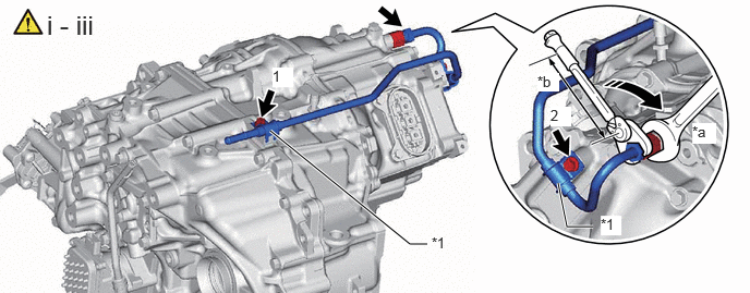
| *1 | No. 2 Oil Cooler Tube Clamp | - | - |
| *a | Hold | *b | Torque Wrench Fulcrum Length |

|
Turn | - | - |
Temporarily install the flare nut of the oil cooler outlet tube sub-assembly to the union.
Install the 2 No. 2 oil cooler tube clamps and oil cooler outlet tube sub-assembly to the FCV with motor transaxle assembly with the 2 bolts in the order shown in the illustration.
- Torque:
- 8.2 N*m (84 kgf*cm, 73 in.*lbf)
Using a 17 mm union nut wrench, tighten the oil cooler outlet tube sub-assembly flare nut.
- Torque:
- Specified Tightening Torque : 34.3 N*m (350 kgf*cm, 25 ft.*lbf)
- HINT:
- ·
Calculate the torque wrench reading when changing the fulcrum length of the torque wrench.
Click hereGeneral>INTRODUCTION>REPAIR INSTRUCTION>PRECAUTION
·When using a 17 mm union nut wrench (fulcrum length of 30 mm (1.18 in.)) + torque wrench (fulcrum length of 180 mm (7.09 in.)):
29.4 N*m (300 kgf*cm, 22 ft.*lbf)
32942G
12.INSTALL NO. 1 OIL COOLER OUTLET HOSE
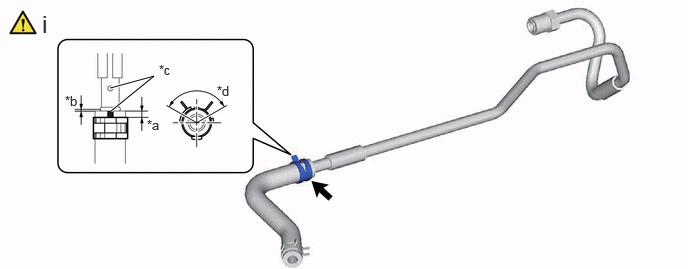
| *a | 2 to 7 mm (0.0787 to 0.275 in.) | *b | 0 to 3 mm (0 to 0.118 in.) |
| *c | Paint Mark (Upper Side of Vehicle) | *d | 120° (Claw of Hose Clip Location) |
Install the No. 1 oil cooler outlet hose to the oil cooler outlet tube sub-assembly and slide the hose clip to secure the hose.
- NOTICE:
- ·
Make sure to slide the No. 1 oil cooler outlet hose until it contacts the hose stopper of the oil cooler outlet tube sub-assembly.
·Make sure to align the paint mark of the No. 1 oil cooler outlet hose with the paint mark of the oil cooler outlet tube sub-assembly.
·Make sure that the claws of the hose clip are within the location shown in the illustration.
46454A
13.INSTALL NO. 4 CABLE SUPPORT BRACKET
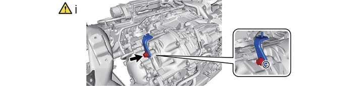
Install the No. 4 cable support bracket to the FCV with motor transaxle assembly with the bolt.
- Torque:
- 23 N*m (235 kgf*cm, 17 ft.*lbf)
- NOTICE:
-
Align the protrusion of the FCV with motor transaxle assembly with the cutout of the No. 4 cable support bracket.
46453A
14.INSTALL NO. 3 CABLE SUPPORT BRACKET
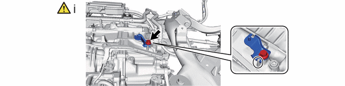
Install the No. 3 cable support bracket to the FCV with motor transaxle assembly with the bolt.
- Torque:
- 23 N*m (235 kgf*cm, 17 ft.*lbf)
- NOTICE:
-
Align the protrusion of the FCV with motor transaxle assembly with the cutout of the No. 3 cable support bracket.
46300
15.INSTALL PARKING BRAKE ACTUATOR ASSEMBLY WITH BRACKET
16.INSTALL OIL COOLER TUBE ASSEMBLY
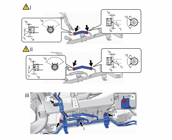
| *a | 2 to 7 mm (0.0787 to 0.275 in.) | *b | 0 to 3 mm (0 to 0.118 in.) |
| *c | Paint Mark | *d | 120° (Claw of Hose Clip Location) |
| *e | Align the protrusion of the oil cooler tube assembly with the cutout of the rear suspension member sub-assembly. | - | - |
Install the No. 2 oil cooler inlet hose to the oil cooler tube sub-assembly and oil cooler without hose tube sub-assembly, and slide the 2 hose clips to secure the hose.
- NOTICE:
- ·
Make sure to slide the No. 2 oil cooler inlet hose until it contacts the hose stopper of the oil cooler tube sub-assembly and oil cooler without hose tube sub-assembly.
·Make sure to align the paint mark of the No. 2 oil cooler inlet hose with the paint mark of the oil cooler tube sub-assembly and oil cooler without hose tube sub-assembly.
·Make sure that the claws of the hose clip are within the location shown in the illustration.
Install the No. 2 oil cooler outlet hose to the oil cooler tube sub-assembly and oil cooler without hose tube sub-assembly, and slide the 2 hose clips to secure the hose.
- NOTICE:
- ·
Make sure to slide the No. 2 oil cooler outlet hose until it contacts the hose stopper of the oil cooler tube sub-assembly and oil cooler without hose tube sub-assembly.
·Make sure to align the paint mark of the No. 2 oil cooler outlet hose with the paint mark of the oil cooler tube sub-assembly and oil cooler without hose tube sub-assembly.
·Make sure that the claws of the hose clip are within the location shown in the illustration.
Install the oil cooler tube sub-assembly to the FCV with motor transaxle assembly with the 4 bolts in the order shown in the illustration.
- Torque:
- 19 N*m (194 kgf*cm, 14 ft.*lbf)
32941M
17.INSTALL NO. 2 OIL COOLER INLET HOSE
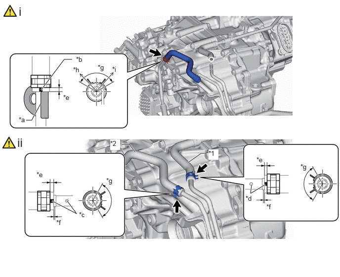
| *1 | No. 1 Oil Cooler Outlet Hose | *2 | No. 2 Oil Cooler Inlet Hose |
| *a | Edge of Oil Cooler Inlet Tube Bracket Sub-assembly | *b | Paint Mark |
| *c | Paint Mark (LH Side of Vehicle) | *d | Paint Mark (RH Side of Vehicle) |
| *e | 2 to 7 mm (0.0787 to 0.275 in.) | *f | 0 to 3 mm (0 to 0.118 in.) |
| *g | 120° (Claw of Hose Clip Location) | *h | Rear Side of Vehicle |
| *i | LH Side of Vehicle | - | - |
Install the No. 2 oil cooler inlet hose to the oil cooler inlet tube sub-assembly and slide the hose clip to secure the hose.
- NOTICE:
- ·
Make sure that the claws of the hose clip are within the location shown in the illustration.
·Make sure to align the paint mark of the oil cooler inlet tube sub-assembly side with the edge of the oil cooler inlet tube bracket.
Connect the No. 1 oil cooler outlet hose and No. 2 oil cooler inlet hose to the oil cooler tube assembly, and slide the 2 hose clips to secure the 2 hoses.
- NOTICE:
- ·
Make sure to slide the No. 1 oil cooler outlet hose and No. 2 oil cooler inlet hose until it contacts the hose stopper of the oil cooler tube assembly.
·Make sure to align the paint mark of the No. 1 oil cooler outlet hose and No. 2 oil cooler inlet hose with the paint mark of the oil cooler tube assembly.
·Make sure that the claws of the hose clip are within the location shown in the illustration.
18.CONNECT WIRE HARNESS
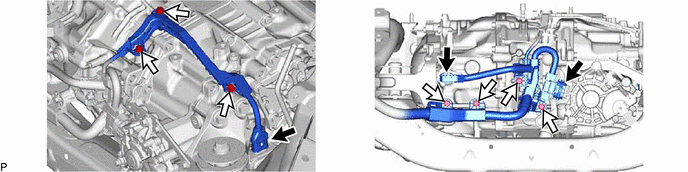
|
|
Wire Harness Connector |
|
Bolt |
- Torque:
- 10 N*m (102 kgf*cm, 7 ft.*lbf)
48812
19.INSTALL REAR STABILIZER BAR
|
|
Click here()
|
82001
20.INSTALL NO. 1 BOND CABLE
- Torque:
- 6.0 N*m (61 kgf*cm, 53 in.*lbf)
G1148
21.INSTALL MOTOR CABLE
|
|
Click here()
|
G114D
22.INSTALL MOTOR CABLE TERMINAL CAP
|
|
Click here()
|
82821T
23.INSTALL CONNECTOR COVER
|
|
Click here()
|
35563
24.INSTALL SHIFT CONTROL ACTUATOR SEAL
|
|
Click here()
|
35580
25.INSTALL SHIFT CONTROL ACTUATOR ASSEMBLY
|
|
Click here()
|
51206A
26.INSTALL REAR SUSPENSION MEMBER SUB-ASSEMBLY