REAR SUSPENSION REAR SUSPENSION MEMBER INSTALLATION
CAUTION / NOTICE / HINT
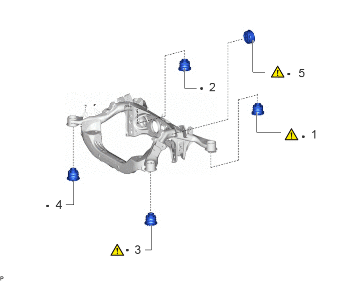
| Procedure | Part Name Code | 
|

|

|
|
|---|---|---|---|---|---|
| 1 | REAR SUSPENSION MEMBER REAR BODY MOUNTING CUSHION (for LH Side) | 52275A | ( ) |
- | - |
| 2 | REAR SUSPENSION MEMBER REAR BODY MOUNTING CUSHION (for RH Side) | 52275A | - | - | - |
| 3 | REAR SUSPENSION MEMBER FRONT BODY MOUNTING CUSHION LH | 52272A | ()
|
- | - |
| 4 | REAR SUSPENSION MEMBER FRONT BODY MOUNTING CUSHION RH | 52271E | - | - | - |
| 5 | REAR MOTOR MOUNTING INSULATOR | G2371A | ()
|
- | - |
| ● | Non-reusable part | - | - |
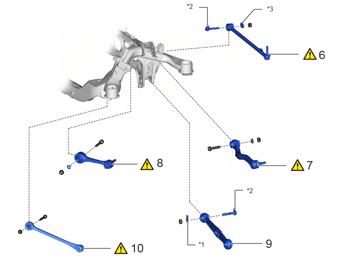
| Procedure | Part Name Code |
|
|
|
|
|---|---|---|---|---|---|
| 6 | TEMPORARILY TIGHTEN TOE CONTROL LINK SUB-ASSEMBLY LH | 48706B | ()
|
- | - |
| 7 | TEMPORARILY TIGHTEN REAR UPPER CONTROL ARM ASSEMBLY LH | 48790 | ()
|
- | - |
| 8 | TEMPORARILY TIGHTEN REAR NO. 1 SUSPENSION ARM ASSEMBLY LH | 48720A | ()
|
- | - |
| 9 | TEMPORARILY TIGHTEN REAR NO. 2 SUSPENSION ARM ASSEMBLY LH | 48740F | - | - | - |
| 10 | TEMPORARILY TIGHTEN LOWER CONTROL ARM ASSEMBLY LH | 48730 | ()
|
- | - |
| *1 | REAR NO. 2 SUSPENSION TOE ADJUST PLATE | *2 | REAR SUSPENSION ARM ATTACHMENT SUB-ASSEMBLY |
| *3 | REAR SUSPENSION TOE ADJUST CAM SUB-ASSEMBLY | - | - |
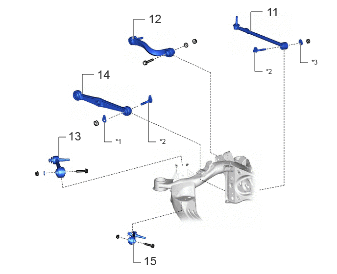
| Procedure | Part Name Code |
|
|
|
|
|---|---|---|---|---|---|
| 11 | TEMPORARILY TIGHTEN TOE CONTROL LINK SUB-ASSEMBLY RH | 48706B | - | - | - |
| 12 | TEMPORARILY TIGHTEN REAR UPPER CONTROL ARM ASSEMBLY RH | 48790 | - | - | - |
| 13 | TEMPORARILY TIGHTEN REAR NO. 1 SUSPENSION ARM ASSEMBLY RH | 48720A | - | - | - |
| 14 | TEMPORARILY TIGHTEN REAR NO. 2 SUSPENSION ARM ASSEMBLY RH | 48740F | - | - | - |
| 15 | TEMPORARILY TIGHTEN LOWER CONTROL ARM ASSEMBLY RH | 48730 | - | - | - |
| *1 | REAR NO. 2 SUSPENSION TOE ADJUST PLATE | *2 | REAR SUSPENSION ARM ATTACHMENT SUB-ASSEMBLY |
| *3 | REAR SUSPENSION TOE ADJUST CAM SUB-ASSEMBLY | - | - |
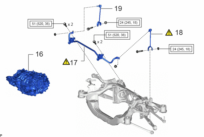
| Procedure | Part Name Code |
|
|
|
|
|---|---|---|---|---|---|
| 16 | FCV WITH MOTOR TRANSAXLE ASSEMBLY | 30600R | - | - | - |
| 17 | REAR STABILIZER BAR | 48812 | ()
|
- | - |
| 18 | TEMPORARILY TIGHTEN REAR STABILIZER LINK ASSEMBLY LH | 48840A | ()
|
- | - |
| 19 | TEMPORARILY TIGHTEN REAR STABILIZER LINK ASSEMBLY RH | 48830D | - | - | - |

|
Tightening torque for "Major areas involving basic vehicle performance such as moving/turning/stopping" : N*m (kgf*cm, ft.*lbf) | - | - |
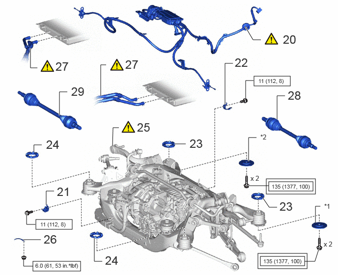
| Procedure | Part Name Code |
|
|
|
|
|---|---|---|---|---|---|
| 20 | PARKING BRAKE WITH BRACKET ACTUATOR ASSEMBLY | 46300 | ()
|
- | - |
| 21 | NO. 2 MOTOR CABLE BRACKET | G1143 | - | - | - |
| 22 | MOTOR CABLE BRACKET | G1143F | - | - | - |
| 23 | REAR UPPER REAR SUSPENSION MEMBER STOPPER | 52278C | - | - | - |
| 24 | REAR LOWER SUSPENSION MEMBER STOPPER | 52277B | - | - | - |
| 25 | REAR SUSPENSION MEMBER SUB-ASSEMBLY | 51206A | ()
|
- | - |
| 26 | NO. 1 BOND CABLE | 82001 | - | - | - |
| 27 | OIL COOLER TUBE SUB-ASSEMBLY | 32906F | ()
|
- | - |
| 28 | REAR DRIVE SHAFT ASSEMBLY LH | 42340B | - | - | - |
| 29 | REAR DRIVE SHAFT ASSEMBLY RH | 42330 | - | - | - |
| *1 | REAR LOWER SUSPENSION MEMBER STOPPER LH | *2 | REAR LOWER SUSPENSION MEMBER STOPPER RH |
|
|
Tightening torque for "Major areas involving basic vehicle performance such as moving/turning/stopping" : N*m (kgf*cm, ft.*lbf) | 
|
N*m (kgf*cm, ft.*lbf): Specified torque |
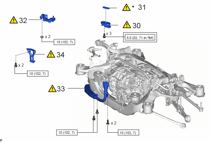
| Procedure | Part Name Code |
|
|
|
|
|---|---|---|---|---|---|
| 30 | WIRING HARNESS CONNECTOR | 82H24 | ()
|
- | - |
| 31 | MOTOR CABLE TERMINAL CAP | G114D | ()
|
- | - |
| 32 | CONNECTOR COVER | 82821T | ()
|
- | - |
| 33 | MOTOR CABLE | G1148 | ()
|
- | - |
| 34 | MOTOR CABLE BRACKET | G1143 | ()
|
- | - |
|
|
Tightening torque for "Major areas involving basic vehicle performance such as moving/turning/stopping" : N*m (kgf*cm, ft.*lbf) |
|
N*m (kgf*cm, ft.*lbf): Specified torque |
| ● | Non-reusable part | - | - |
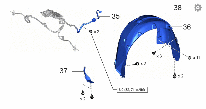
| Procedure | Part Name Code |
|
|
|
|
|---|---|---|---|---|---|
| 35 | PARKING BRAKE WITH BRACKET ACTUATOR ASSEMBLY | 46300 | - | - | - |
| 36 | REAR WHEEL HOUSE LINER LH | 65638 | - | - | - |
| 37 | ROCKER PANEL MOULDING PROTECTOR LH | 75866E | - | - | - |
| 38 | STABILIZE SUSPENSION | - | - | - | ()
|
|
|
N*m (kgf*cm, ft.*lbf): Specified torque | - | - |
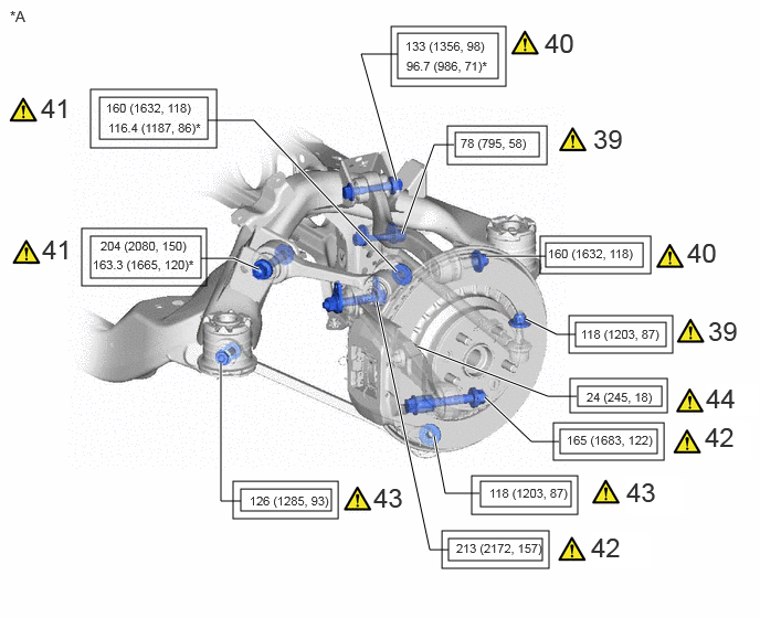
| Procedure | Part Name Code |
|
|
|
|
|---|---|---|---|---|---|
| 39 | FULLY TIGHTEN TOE CONTROL LINK SUB-ASSEMBLY LH | 48706B | ()
|
- | - |
| 40 | FULLY TIGHTEN REAR UPPER CONTROL ARM ASSEMBLY LH | 48790 | ()
|
- | - |
| 41 | FULLY TIGHTEN REAR NO. 1 SUSPENSION ARM ASSEMBLY LH | 48720A | ()
|
- | - |
| 42 | FULLY TIGHTEN REAR NO. 2 SUSPENSION ARM ASSEMBLY LH | 48740F | ()
|
- | - |
| 43 | FULLY TIGHTEN LOWER CONTROL ARM ASSEMBLY LH | 48730 | ()
|
- | - |
| 44 | FULLY TIGHTEN REAR STABILIZER LINK ASSEMBLY LH | 48840A | ()
|
- | - |
| *A | for LH Side | - | - |
|
|
Tightening torque for "Major areas involving basic vehicle performance such as moving/turning/stopping" : N*m (kgf*cm, ft.*lbf) | * | For use with ball joint lock nut wrench |
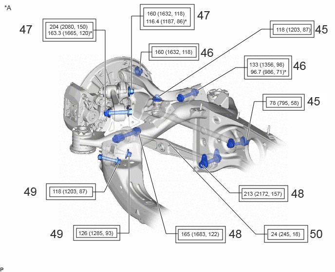
| Procedure | Part Name Code |
|
|
|
|
|---|---|---|---|---|---|
| 45 | FULLY TIGHTEN TOE CONTROL LINK SUB-ASSEMBLY RH | 48706B | - | - | - |
| 46 | FULLY TIGHTEN REAR UPPER CONTROL ARM ASSEMBLY RH | 48790 | - | - | - |
| 47 | FULLY TIGHTEN REAR NO. 1 SUSPENSION ARM ASSEMBLY RH | 48720A | - | - | - |
| 48 | FULLY TIGHTEN REAR NO. 2 SUSPENSION ARM ASSEMBLY RH | 48740F | - | - | - |
| 49 | FULLY TIGHTEN LOWER CONTROL ARM ASSEMBLY RH | 48730 | - | - | - |
| 50 | FULLY TIGHTEN REAR STABILIZER LINK ASSEMBLY RH | 48830D | - | - | - |
| *A | for RH Side | - | - |
|
|
Tightening torque for "Major areas involving basic vehicle performance such as moving/turning/stopping" : N*m (kgf*cm, ft.*lbf) | * | For use with ball joint lock nut wrench |
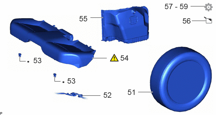
| Procedure | Part Name Code |
|
|
|
|
|---|---|---|---|---|---|
| 51 | REAR TIRE | - | - | - | - |
| 52 | WIRE HARNESS | - | - | - | - |
| 53 | REAR SEAT CUSHION LOCK HOOK | 72693 | - | - | - |
| 54 | REAR SEAT CUSHION ASSEMBLY | - | ()
|
- | - |
| 55 | INNER LUGGAGE COMPARTMENT TRIM COVER LH | 64721 | - | - | - |
| 56 | ADD HYBRID TRANSAXLE FLUID | - | - | ()
|
- |
| 57 | INSPECT HYBRID TRANSAXLE FLUID | - | - | - | ()
|
| 58 | INSPECT AIR FROM HYBRID TRANSAXLE FLUID | - | - | - | ()
|
| 59 | INSPECT FOR HYBRID TRANSAXLE FLUID LEAK | - | - | - | ()
|
| ● | Non-reusable part | - | - |
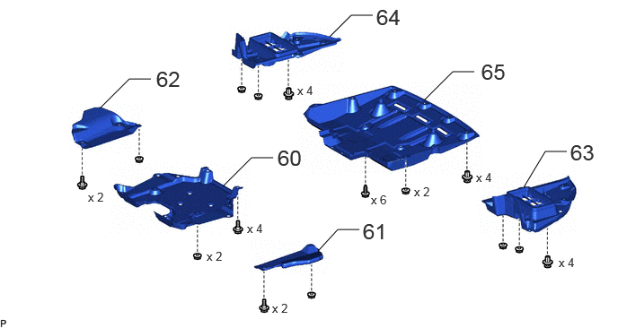
| Procedure | Part Name Code |
|
|
|
|
|---|---|---|---|---|---|
| 60 | REAR SUSPENSION BRACE COVER | 53661B | - | - | - |
| 61 | NO. 1 DIFFERENTIAL SUPPORT PROTECTOR | 52383E | - | - | - |
| 62 | NO. 2 DIFFERENTIAL SUPPORT PROTECTOR | 52384C | - | - | - |
| 63 | TRANSMISSION OIL COOLER UNDER COVER LH | 32912B | - | - | - |
| 64 | TRANSMISSION OIL COOLER UNDER COVER RH | 32911 | - | - | - |
| 65 | NO.1 FLOOR UNDER COVER | 58398F | - | - | - |
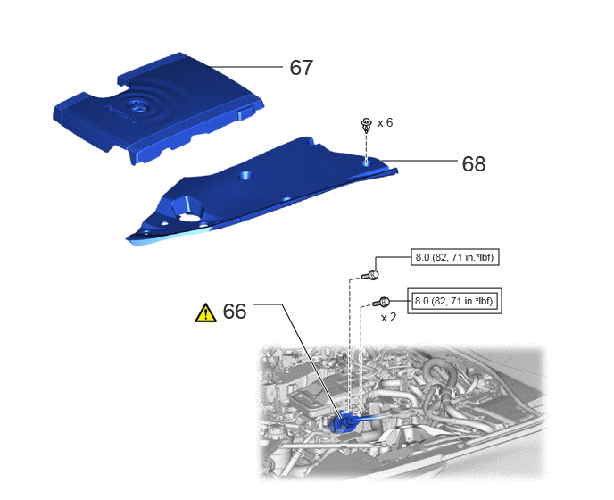
| Procedure | Part Name Code |
|
|
|
|
|---|---|---|---|---|---|
| 66 | FC CONVERTER POWER OUTLET CABLE (INVERTER WITH CONVERTER ASSEMBLY) | G9200A | ()
|
- | - |
| 67 | FC STACK COVER SUB-ASSEMBLY | 1A906 | - | - | - |
| 68 | UPPER RADIATOR SUPPORT SEAL | 53292A | - | - | - |
|
|
Tightening torque for "Major areas involving basic vehicle performance such as moving/turning/stopping" : N*m (kgf*cm, ft.*lbf) |
|
N*m (kgf*cm, ft.*lbf): Specified torque |
| Procedure | Part Name Code |
|
|
|
|
|---|---|---|---|---|---|
| 69 | SERVICE PLUG GRIP | G3834 | - | - | - |
| 70 | INSPECT AND ADJUST REAR WHEEL ALIGNMENT | - | - | - | - |
| 71 | ADJUST PARKING BRAKE | - | - | - | ()
|
| 72 | CHECK FOR SPEED SENSOR SIGNAL | - | - | - | ()
|
| 73 | INITIALIZATION AFTER RECONNECTING BATTERY TERMINAL | - | - | - | ()
|
| 74 | PERFORM INITIALIZATION | - | - | - | ()
|
PROCEDURE

 52275A
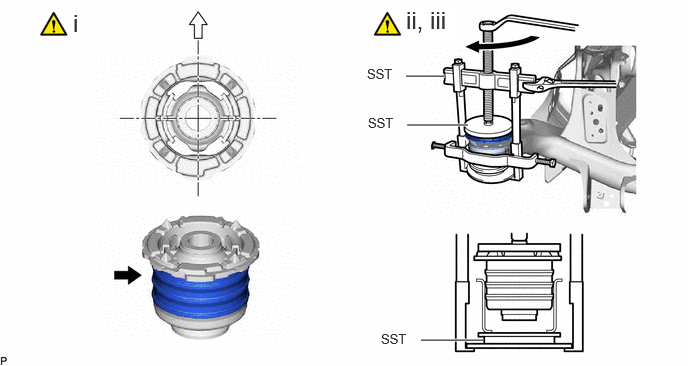
1.INSTALL REAR SUSPENSION MEMBER REAR BODY MOUNTING CUSHION (for LH Side)

|
Diluted Liquid Soap | 
|
Front of the Vehicle |
Apply diluted liquid soap to the outside of a new rear suspension member rear body mounting cushion.
- NOTICE:
-
Do not use grease or undiluted liquid soap. Doing so may cause the rear suspension member front body mounting cushion to slip out.
- HINT:
-
A 20% liquid soap and water concentration is recommended.
Temporarily install the rear suspension member rear body mounting cushion while confirming the installation direction.
Using SST, install the rear suspension member rear body mounting cushion until there is no clearance between the rear suspension member sub-assembly and rear suspension member rear body mounting cushion.
- SST
- 09316-12010
09570-24011
09950-40011 (09951-04020, 09952-04010, 09953-04030, 09954-04020, 09955-04051, 09957-04010, 09958-04011)
09950-60021 (09951-00910)
- NOTICE:
-
Apply grease to the threads and tip of the SST center bolt before use.
52275A
2.INSTALL REAR SUSPENSION MEMBER REAR BODY MOUNTING CUSHION (for RH Side)
Perform the same procedure as for the LH side.
52272A
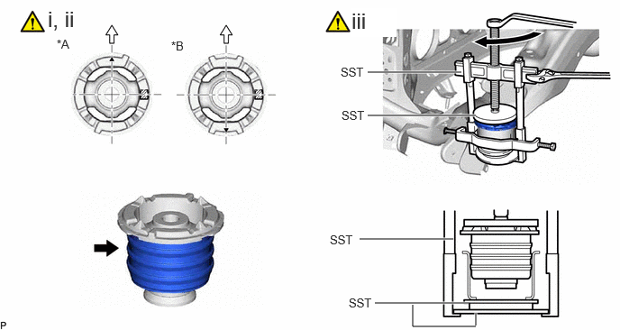
3.INSTALL REAR SUSPENSION MEMBER FRONT BODY MOUNTING CUSHION LH
| *A | for LH Side | *B | for RH Side |
|
|
Diluted Liquid Soap |
|
Front of the Vehicle |
Apply diluted liquid soap to the outside of a new rear suspension member front body mounting cushion.
- NOTICE:
-
Do not use grease or undiluted liquid soap. Doing so may cause the rear suspension member front body mounting cushion to slip out.
- HINT:
-
A 20% liquid soap and water concentration is recommended.
Temporarily install the rear suspension member front body mounting cushion while confirming the installation direction.
Using SST, install the rear suspension member front body mounting cushion until there is no clearance between the rear suspension member sub-assembly and rear suspension member front body mounting cushion.
- SST
- 09316-12010
09570-24011
09950-40011 (09951-04020, 09952-04010, 09953-04030, 09954-04020, 09955-04051, 09957-04010, 09958-04011)
09950-60021 (09951-00910)
- NOTICE:
-
Apply grease to the threads and tip of the SST center bolt before use.
52271E
4.INSTALL REAR SUSPENSION MEMBER FRONT BODY MOUNTING CUSHION RH
Perform the same procedure as for the LH side.
G2371A
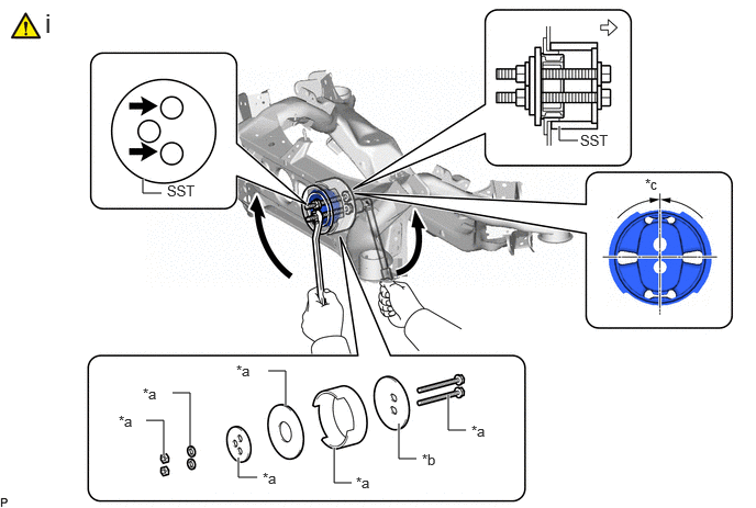
5.INSTALL REAR MOTOR MOUNTING INSULATOR
| *a | SST (09570-48010) | *b | SST (09570-24011) |
| *c | 0° +/- 3° | - | - |
|
|
SST bolt location |
|
Front of the Vehicle |
Using SST, install a new rear motor mounting insulator.
- SST
- 09570-24011
09570-48010
- NOTICE:
- ·
Make sure that the rear motor mounting insulator is aligned within 3° from the center.
·Temporarily install the rear motor mounting insulator to the rear suspension member sub-assembly in order to prevent it from tilting, and then install SST.
·Before using SST, apply grease to the SST bolts.
·Be sure to use the correct combination of SST.
·Do not tilt the bolts of SST.
·Tighten the 2 bolts of SST so that they enter the 2 holes of the rear motor mounting insulator by an equal amount.
- HINT:
-
Install the 2 SST bolts to the 2 SST holes as shown in the illustration.
48706B
6.TEMPORARILY TIGHTEN TOE CONTROL LINK SUB-ASSEMBLY LH
|
|
()
|
48790
7.TEMPORARILY TIGHTEN REAR UPPER CONTROL ARM ASSEMBLY LH
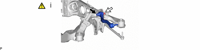
|
|
Bolt |
|
Nut |
Insert the bolt from the front of the vehicle. Then temporarily tighten the rear upper control arm assembly LH with the nut and washer.
48720A
8.TEMPORARILY TIGHTEN REAR NO. 1 SUSPENSION ARM ASSEMBLY LH
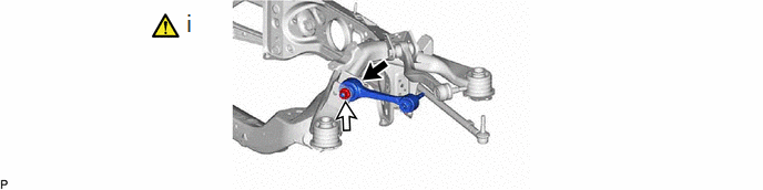
|
|
Bolt |
|
Nut |
Insert the bolt from the back of the vehicle. Then temporarily tighten the rear No. 1 suspension arm assembly LH with the nut and washer.
48740F
9.TEMPORARILY TIGHTEN REAR NO. 2 SUSPENSION ARM ASSEMBLY LH
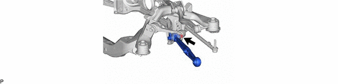
48730
10.TEMPORARILY TIGHTEN LOWER CONTROL ARM ASSEMBLY LH
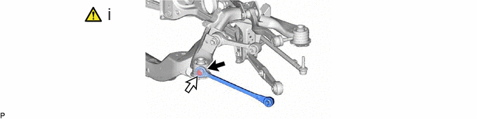
|
|
Bolt |
|
Nut |
Insert the bolt from the back of the vehicle. Then temporarily tighten the lower control arm assembly LH with the nut.
48705
11.TEMPORARILY TIGHTEN TOE CONTROL LINK SUB-ASSEMBLY RH
Perform the same procedure as for the LH side.
48770A
12.TEMPORARILY TIGHTEN REAR UPPER CONTROL ARM ASSEMBLY RH
Perform the same procedure as for the LH side.
48710A
13.TEMPORARILY TIGHTEN REAR NO. 1 SUSPENSION ARM ASSEMBLY RH
Perform the same procedure as for the LH side.
48730F
14.TEMPORARILY TIGHTEN REAR NO. 2 SUSPENSION ARM ASSEMBLY RH
Perform the same procedure as for the LH side.
48720
15.TEMPORARILY TIGHTEN LOWER CONTROL ARM ASSEMBLY RH
Perform the same procedure as for the LH side.
30600R
16.INSTALL FCV WITH MOTOR TRANSAXLE ASSEMBLY
48812
17.INSTALL REAR STABILIZER BAR
|
|
Click here()
|
48840A
18.TEMPORARILY TIGHTEN REAR STABILIZER LINK ASSEMBLY LH
|
|
Click here()
|
48830D
19.TEMPORARILY TIGHTEN REAR STABILIZER LINK ASSEMBLY RH
Perform the same procedure as for the LH side.
46300
20.INSTALL PARKING BRAKE WITH BRACKET ACTUATOR ASSEMBLY
G1143F
21.INSTALL NO. 2 MOTOR CABLE BRACKET
- Torque:
- 11 N*m (112 kgf*cm, 8 ft.*lbf)
G1143
22.INSTALL MOTOR CABLE BRACKET
- Torque:
- 11 N*m (112 kgf*cm, 8 ft.*lbf)
52277B
23.INSTALL REAR UPPER REAR SUSPENSION MEMBER STOPPER
52278C
24.INSTALL REAR LOWER SUSPENSION MEMBER STOPPER
51206A
25.INSTALL REAR SUSPENSION MEMBER SUB-ASSEMBLY
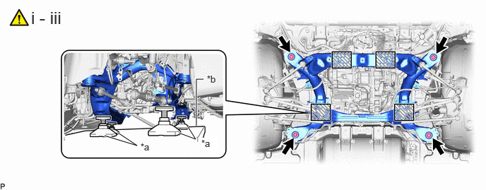
| *a | Attachment | *b | Engine Lifter |

|
Attachment placement location | - | - |
Support the rear suspension member sub-assembly with an engine lifter using 4 attachments or equivalent tools as shown in the illustration.
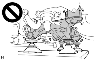
- CAUTION:
-
- ·
The rear suspension member sub-assembly is a very heavy component. Make sure that it is supported securely.
·If the rear suspension member sub-assembly is not securely supported, it may drop, resulting in serious injury.
- NOTICE:
-
Use attachments to keep the rear suspension member sub-assembly level.
Raise the rear suspension member sub-assembly until there is no clearance between the rear suspension member sub-assembly and vehicle body.
- NOTICE:
-
When raising the rear suspension member sub-assembly, be careful not to damage the vehicle body or other components installed to the vehicle.
Install the rear lower suspension member stopper LH, rear lower suspension member stopper RH and rear suspension member sub-assembly with the 4 bolts.
- Torque:
- 135 N*m (1377 kgf*cm, 100 ft.*lbf)
82001
26.INSTALL NO. 1 BOND CABLE
- Torque:
- 6.0 N*m (61 kgf*cm, 53 in.*lbf)
32906F
27.INSTALL OIL COOLER TUBE SUB-ASSEMBLY
|
|
()
|
42340B
28.INSTALL REAR DRIVE SHAFT ASSEMBLY LH
42330
29.INSTALL REAR DRIVE SHAFT ASSEMBLY RH
Perform the same procedure as for the LH side.
82H24
30.INSTALL WIRING HARNESS CONNECTOR
|
|
|
- Torque:
- 8.0 N*m (82 kgf*cm, 71 in.*lbf)
G114D
31.INSTALL MOTOR CABLE TERMINAL CAP
|
|
|
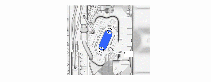
| *1 | Seal Rubber | - | - |
82821T
32.INSTALL CONNECTOR COVER
|
|
|
- Torque:
- 10 N*m (102 kgf*cm, 7 ft.*lbf)
G1148
33.INSTALL MOTOR CABLE
|
|
|
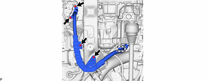
- Torque:
- 10 N*m (102 kgf*cm, 7 ft.*lbf)
G1143
34.INSTALL MOTOR CABLE BRACKET
|
|
|
- Torque:
- 10 N*m (102 kgf*cm, 7 ft.*lbf)
46300
35.CONNECT PARKING BRAKE WITH BRACKET ACTUATOR ASSEMBLY
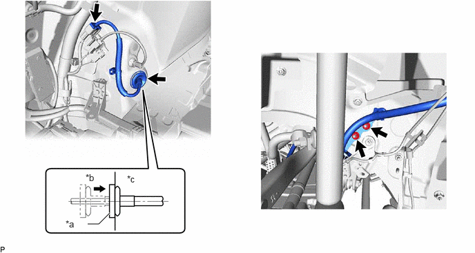
| *a | Grommet | *b | Outside of Vehicle |
| *c | Inside of Vehicle | - | - |
- Torque:
- 8.0 N*m (82 kgf*cm, 71 in.*lbf)
65638
36.INSTALL REAR WHEEL HOUSE LINER LH
75866E
37.INSTALL ROCKER PANEL MOULDING PROTECTOR LH
38.STABILIZE SUSPENSION
|
|
Click here()
|
48706B
39.FULLY TIGHTEN TOE CONTROL LINK SUB-ASSEMBLY LH
|
|
Click here()
|
48790
40.FULLY TIGHTEN REAR UPPER CONTROL ARM ASSEMBLY LH
|
|
Click here()
|
48720A
41.FULLY TIGHTEN REAR NO. 1 SUSPENSION ARM ASSEMBLY LH
|
|
Click here()
|
48740F
42.FULLY TIGHTEN REAR NO. 2 SUSPENSION ARM ASSEMBLY LH
48730
43.FULLY TIGHTEN LOWER CONTROL ARM ASSEMBLY LH
|
|
Click here()
|
48840A
44.FULLY TIGHTEN REAR STABILIZER LINK ASSEMBLY LH
|
|
Click here()
|
48705
45.FULLY TIGHTEN TOE CONTROL LINK SUB-ASSEMBLY RH
Perform the same procedure as for the LH side.
48770A
46.FULLY TIGHTEN REAR UPPER CONTROL ARM ASSEMBLY RH
Perform the same procedure as for the LH side.
48710A
47.FULLY TIGHTEN REAR NO. 1 SUSPENSION ARM ASSEMBLY RH
Perform the same procedure as for the LH side.
48730F
48.FULLY TIGHTEN REAR NO. 2 SUSPENSION ARM ASSEMBLY RH
Perform the same procedure as for the LH side.
48720
49.FULLY TIGHTEN LOWER CONTROL ARM ASSEMBLY RH
Perform the same procedure as for the LH side.
48830D
50.FULLY TIGHTEN REAR STABILIZER LINK ASSEMBLY RH
Perform the same procedure as for the LH side.
51.INSTALL REAR TIRE
Perform the same procedure as for the LH side.
52.INSTALL WIRE HARNESS
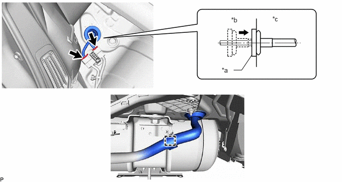
| *a | Grommet | *b | Outside of Vehicle |
| *c | Inside of Vehicle | - | - |
72693
53.INSTALL REAR SEAT CUSHION LOCK HOOK
54.INSTALL REAR SEAT CUSHION ASSEMBLY
|
|
Click here()
|
64722
55.INSTALL LUGGAGE COMPARTMENT TRIM COVER INNER LH
56.ADD HYBRID TRANSAXLE FLUID
|
|
Click here()
|
57.INSPECT HYBRID TRANSAXLE FLUID
|
|
Click here()
|
58.BLEED AIR FROM HYBRID TRANSAXLE FLUID
|
|
Click here()
|
59.INSPECT FOR HYBRID TRANSAXLE FLUID LEAK
|
|
Click here()
|
53661B
60.INSTALL REAR SUSPENSION BRACE COVER
52383E
61.INSTALL NO. 1 DIFFERENTIAL SUPPORT PROTECTOR
52384C
62.INSTALL NO. 2 DIFFERENTIAL SUPPORT PROTECTOR
32912B
63.INSTALL TRANSMISSION OIL COOLER UNDER COVER LH
32911
64.INSTALL TRANSMISSION OIL COOLER UNDER COVER RH
58398F
65.INSTALL NO.1 FLOOR UNDER COVER
G9200A
66.CONNECT FC CONVERTER POWER OUTLET CABLE (INVERTER WITH CONVERTER ASSEMBLY)
|
|
Click here()
|
1A906
67.INSTALL FC STACK COVER SUB-ASSEMBLY
53292A
68.INSTALL UPPER RADIATOR SUPPORT SEAL
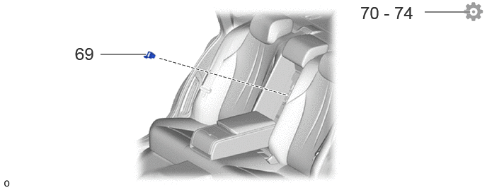
G3834
69.INSTALL SERVICE PLUG GRIP
70.INSPECT AND ADJUST REAR WHEEL ALIGNMENT
71.ADJUST PARKING BRAKE
72.CHECK FOR SPEED SENSOR SIGNAL
73. INITIALIZATION AFTER RECONNECTING BATTERY TERMINAL
Click hereGeneral>SETUP>WHEN DISCONNECTING OR RECONNECTING BATTERY TERMINAL>WORK PROCEDURE
- HINT:
-
When disconnecting and reconnecting the battery, there is an automatic learning function that completes learning when the respective system is used.
-
Click hereGeneral>SETUP>WHEN DISCONNECTING OR RECONNECTING BATTERY TERMINAL>AUTOMATIC LEARNING CHART
74.PERFORM INITIALIZATION