HYBRID / BATTERY CONTROL HYBRID CONTROL SYSTEM P0ABF00 Hybrid/EV Battery Current Sensor "A" Circuit Range/Performance
DESCRIPTION
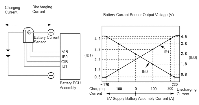
A battery current sensor, which is mounted on the positive cable side of each EV supply battery, detects the current flowing to or from the battery pack. The battery current sensor sends a voltage, which varies between 0 and 5 V in proportion to the amperage, to the IB0 terminal of the battery ECU assembly. Similarly, it sends a voltage, which varies between 0 and 5 V in inverse proportion to the amperage, to the IB1 terminal of the battery ECU assembly. When the voltage at the IB0 terminal is below 2.8 V and the voltage at the IB1 terminal is above 2.2 V, this indicates that the EV supply battery assembly is being discharged. Additionally, Meanwhile, when the voltage at of the IB0 terminal is above 2.8 V and the voltage at of the IB1 terminal is below 2.2 V, this indicates that the EV supply battery assembly is being charged. The battery ECU assembly sends the signals from its IB0 and IB1 terminals to the EV control ECU. The EV control ECU determines the charging and discharging amperage of the EV supply battery assembly based on the received signals and calculates the SOC of the EV supply battery assembly using the cumulative amperage value.
| DTC No. | Detection Item | DTC Detection Condition | Trouble Area | Warning Indicate | DTC Output from | Priority |
|---|---|---|---|---|---|---|
| P0ABF00 | Hybrid/EV Battery Current Sensor "A" Circuit Range/Performance | Abnormal battery current sensor characteristics:
(based on hybrid system consumption and EV supply battery assembly output). (1 trip detection logic) |
·
No. 1 EV battery junction block assembly ·
Battery ECU assembly ·
Wire harness or connector |
Master Warning:
Comes on |
EV | A |
| DTC No. | Data List |
|---|---|
| P0ABF00 | - |
CONFIRMATION DRIVING PATTERN
- HINT:
-
After repair has been completed, clear the DTC and then check that the vehicle has returned to normal by performing the following All Readiness check procedure.
-
Click hereEngine / Hybrid System>HYBRID / BATTERY CONTROL>HYBRID CONTROL SYSTEM>UTILITY
Clear the DTCs (even if no DTCs are stored, perform the clear DTC procedure).
Turn the ignition switch off and wait for 10 minutes or more.
Drive the vehicle for approximately 10 minutes according to the freeze frame data items "Vehicle Speed", "Accelerator Position", "Hybrid/EV Battery Current", "Motor Torque Estimate Value" and "FC Air Compressor Motor Torque Estimate Value".
Enter the following menus: Powertrain / EV / Utility / All Readiness.
Check the DTC judgment result.
- HINT:
- ·
If the judgment result shows NORMAL, the system is normal.
·If the judgment result shows ABNORMAL, the system has a malfunction.
·If the judgment result shows INCOMPLETE, perform driving pattern again.
WIRING DIAGRAM
Refer to the wiring diagram for DTC P0ABF11.
Click hereEngine / Hybrid System>HYBRID / BATTERY CONTROL>HYBRID BATTERY SYSTEM>P0ABF11
CAUTION / NOTICE / HINT
- CAUTION:
- ·
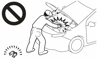
Before the following operations are conducted, take precautions to prevent electric shock by turning the ignition switch off, wearing insulated gloves, and removing the EV battery service plug grip and FC converter power outlet cable on FC converter side.
Make sure to remove the service plug grip first.
-Inspecting the high-voltage system
-Disconnecting the low voltage connector of the inverter with converter assembly
-Disconnecting the low voltage connector of the EV supply battery assembly
-Disconnecting the low voltage connector of the FC converter assembly
-Disconnecting the low voltage connector of the voltage inverter (for 1500W Type Voltage Inverter)
·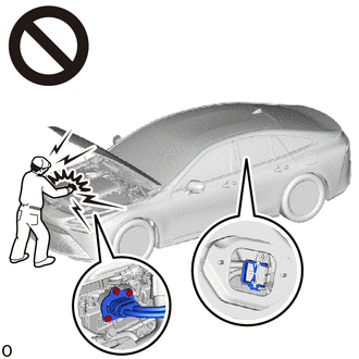
To prevent electric shock, make sure to remove the EV battery service plug grip and FC converter power outlet cable on FC converter side to cut off the high voltage circuit before servicing the vehicle.
·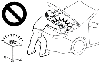
After removing the EV battery service plug grip and FC converter power outlet cable on FC converter side, store them according to the following guidelines to prevent other technicians from accidentally reconnecting them while work is being performed on the high voltage systems.
-The technician performing the work should put the EV battery service plug grip in their pocket and carry it with them.
-Remove the FC converter power outlet cable on FC converter side with a "HIGH-VOLTAGE, DO NOT TOUCH" caution tag attached to it for other technicians.
·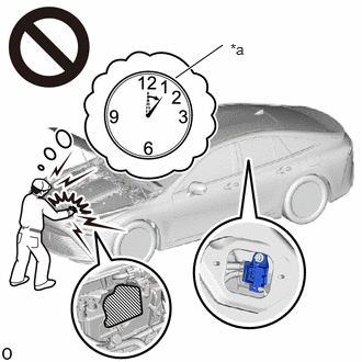 1.667,0.74 2.115,0.427 true 2.188,0.385 2.448,0.552 0.26,0.167 10 false *a
*a Without waiting for 10 minutes
After removing the EV battery service plug grip and FC converter power outlet cable on FC converter side, wait for at least 10 minutes before touching any of the high-voltage connectors or terminals. After waiting for 10 minutes, check the voltage at the terminals in the inspection point in the inverter with converter assembly. The voltage should be 0 V before beginning work.
Click hereEngine / Hybrid System>HYBRID / BATTERY CONTROL>HYBRID CONTROL SYSTEM>PRECAUTION
- HINT:
-
Waiting for at least 10 minutes is required to discharge the high-voltage capacitor inside the inverter with converter assembly and the electric vehicle charger assembly.
·Make sure to insulate the high-voltage connectors and terminals of the EV supply battery assembly with insulating tape after removing it.
If the EV supply battery assembly stored without insulating the connectors and terminals, electric shock or fire may result.
·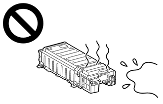
After removing the EV supply battery assembly, keep it away from water. Exposure to water may cause the EV supply battery assembly to produce heat, resulting in a fire.
- NOTICE:
- ·
After turning the ignition switch off, there may be a waiting time before disconnecting the auxiliary negative (-) battery terminal.
Click hereGeneral>SETUP>WHEN DISCONNECTING OR RECONNECTING BATTERY TERMINAL>BEFORE DISCONNECTING BATTERY
·When disconnecting and reconnecting the auxiliary battery.
Click hereGeneral>SETUP>WHEN DISCONNECTING OR RECONNECTING BATTERY TERMINAL>WORK PROCEDURE
- HINT:
-
When disconnecting and reconnecting the auxiliary battery, there is an automatic learning function that completes learning when the respective system is used.
-
Click hereGeneral>SETUP>WHEN DISCONNECTING OR RECONNECTING BATTERY TERMINAL>AUTOMATIC LEARNING CHART
·This vehicle performs FC system shutdown process after turning the ignition switch off from ON (READY). Therefore, after the ignition switch is turned off from ON (READY), do not perform any work on the electrical system for at least 10 minutes including removing connectors or disconnecting the negative (-) auxiliary battery terminal.
·When the EV control ECU determines that the temperature of FC system components is below 0°C (32°F) when the vehicle is parked with the ignition switch off, it operates the FC air compressor, hydrogen pump and FC cooling water pump for a maximum of 180 seconds to drain the FC stack assembly. When performing inspection or repairs with the ignition switch off (not ON or ON (READY)), disconnect the cable from the negative (-) auxiliary battery terminal before performing work. (If the auxiliary battery voltage is needed to conduct inspection, perform the inspection in an environment with an ambient temperature of 10°C (50°F) or higher.)
PROCEDURE
Pre-procedure1
None.
Procedure1
Check for DTCs.
- Powertrain > EV Battery > Trouble Codes
- 50001 398
- Powertrain > EV > Trouble Codes
- 50001 397
- Powertrain > FCDC > Trouble Codes
- 50001 493
- Result:
Result Proceed to P0ABF00 is output, or DTCs of hybrid battery system microcomputer malfunction in the tables below are output. A P0ABF00 is output, or DTCs of hybrid control system microcomputer malfunction in the tables below are output. B P0ABF00 is output, or DTCs of FC boost control system Sensor and actuator circuit malfunction in the tables below are output. C Only P0ABF00 is output D
| Malfunction Content | System | Relevant DTC | |
|---|---|---|---|
| Microcomputer malfunction | Hybrid battery system | P060A47 | Hybrid/EV Powertrain Control Module Processor Watchdog / Safety MCU Failure |
| P060B49 | Hybrid/EV Powertrain Control Module A/D Processing Internal Electronic Failure | ||
| P060687 | Hybrid/EV Powertrain Control Module Processor to Monitoring Processor Missing Message | ||
| System malfunction | Hybrid control system | P0A1F94 | Hybrid/EV Battery Energy Control Module Unexpected Operation |
| Sensor and actuator circuit malfunction | FC control system | P1D4F62 | Total Reactor Current/FC Current Signal Compare Failure |
- HINT:
- ·
P0ABF00 may be output as a result of the malfunction indicated by the DTCs above.
(a)The chart above is listed in inspection order of priority.
(b)Check DTCs that are output at the same time by following the listed order. (The main cause of the malfunction can be determined without performing unnecessary inspections.)
Post-procedure1
Turn the ignition switch off.
A
Click hereEngine / Hybrid System>HYBRID / BATTERY CONTROL>HYBRID BATTERY SYSTEM>DIAGNOSTIC TROUBLE CODE CHART
B
C
D
- Result:
Proceed to NEXT
NEXT
NEXT
- CAUTION:
-
Be sure to wear insulated gloves and protective goggles.
Pre-procedure1
Check that the service plug grip and FC converter power outlet cable are not installed.
- NOTICE:
-
After removing the service plug grip and FC converter power outlet cable, do not turn the ignition switch to ON (READY), unless instructed by the repair manual because this may cause a malfunction.
Remove the upper No. 1 EV battery cover sub-assembly.
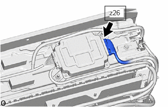
Disconnect the z26 battery ECU assembly connector.
- NOTICE:
-
Before disconnecting the connector, check that it is not loose or disconnected.
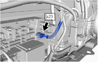
Disconnect the z23 No. 1 EV battery junction block assembly connector.
- NOTICE:
-
Before disconnecting the connector, check that it is not loose or disconnected.
Procedure1
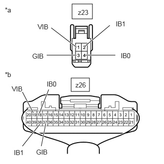
| *a | Front view of wire harness connector
(to No. 1 EV Battery Junction Block Assembly (Battery Current Sensor)) |
| *b | Rear view of wire harness connector
(to Battery ECU Assembly) |
Measure the resistance according to the value(s) in the tables below.
- Standard Resistance:
Tester Connection Condition Specified Condition Click Location & Routing(z26,z23)Location & Routingewd_type=routing;type=c,c;code=z26,z23
Click Connector(z26)Body>other>EV Supply Battery Assembly , Battery ECU Assemblyewd_type=component;type=c;code=z26;pinno=19,38,37,18
Click Connector(z23)Body>other>EV Supply Battery Assembly , No. 1 EV Battery Junction Block Assemblyewd_type=component;type=c;code=z23;pinno=1,2,3,4
z26-19 (VIB) - z23-1 (VIB) Ignition switch off Below 1 Ω z26-38 (IB1) - z23-2 (IB1) Ignition switch off Below 1 Ω z26-37 (GIB) - z23-3 (GIB) Ignition switch off Below 1 Ω z26-18 (IB0) - z23-4 (IB0) Ignition switch off Below 1 Ω z26-19 (VIB) or z23-1 (VIB) - Body ground and other terminals Ignition switch off 10 kΩ or higher z26-38 (IB1) or z23-2 (IB1) - Body ground and other terminals Ignition switch off 10 kΩ or higher z26-37 (GIB) or z23-3 (GIB) - Body ground and other terminals Ignition switch off 10 kΩ or higher z26-18 (IB0) or z23-4 (IB0) - Body ground and other terminals Ignition switch off 10 kΩ or higher
- Result:
Proceed to OK NG
Post-procedure1
Reconnect the z23 No. 1 EV battery junction block assembly connector.
Reconnect the z26 battery ECU assembly connector.
Install the upper No. 1 EV battery cover sub-assembly.
OK
NG
- Result:
Proceed to NEXT
NEXT
Click hereEngine / Hybrid System>HYBRID / BATTERY CONTROL>HYBRID CONTROL SYSTEM>P06881F
- Result:
Proceed to NEXT
NEXT
Pre-procedure1
Check that "Hybrid/EV Battery SOC" shows 60% or less.
- Powertrain > EV > Data List
-
Tester Display Hybrid/EV Battery SOC - 50003 397 320
- HINT:
-
If "Hybrid/EV Battery SOC" is 60% or more, reduce it to below 60% by leaving the hybrid system on with neutral (N) selected.
Apply the parking brake and secure the wheels using chocks.
Turn the ignition switch to ON (READY).
Procedure1
Change the shift position to park (P) and perform the following operation repeatedly for 1 minute or more.
- HINT:
-
Depress and release the accelerator pedal in 5-second intervals (2.5 seconds each) continuously.
Depress the accelerator pedal.
Release the accelerator pedal.
- Result:
Proceed to NEXT
Post-procedure1
Turn the ignition switch off.
NEXT
Pre-procedure1
None.
Procedure1
Check for DTCs.
- Powertrain > EV > Trouble Codes
- 50001 397
- Result:
Result Proceed to P0ABF00 is not output A P0ABF00 is output B
Post-procedure1
Turn the ignition switch off.
A
B