 |
Pass the No. 1 parking brake cable through the pedal bracket and hold it with a new clip.
PARKING BRAKE PEDAL > INSTALLATION |
| 1. INSTALL PARKING PEDAL PAD |
| 2. INSTALL PARKING BRAKE SWITCH ASSEMBLY |
Install the parking brake switch with the screw.
| 3. INSTALL NO. 1 PARKING BRAKE CABLE ASSEMBLY |
|
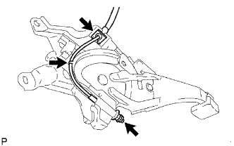
Pass the No. 1 parking brake cable through the pedal bracket and hold it with a new clip.
Pass the parking brake cable through the pedal guide. Temporarily tighten the adjusting nut and lock nut.
Bend the parking brake pedal claw fully.
| 4. INSTALL PARKING BRAKE CONTROL PEDAL ASSEMBLY |
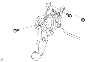 |
Install the parking brake control pedal with the 2 bolts and nut.
Connect the parking brake switch connector and install the harness clamp to the pedal bracket.
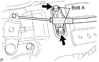 |
Connect the No. 1 parking brake cable to the parking brake intermediate lever.
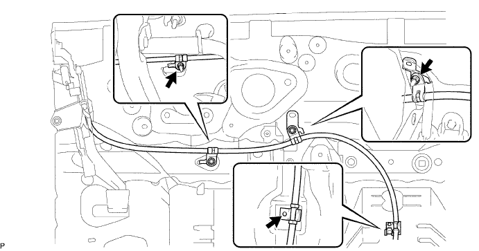
Install the No. 1 parking brake cable on the floor with the 2 bolts labeled A shown in the illustration.
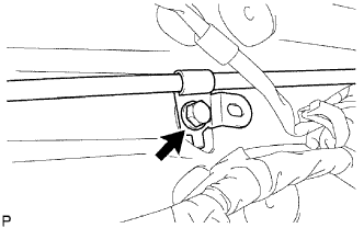 |
Install the No. 1 parking brake cable to the floor with the clamp bolt.
Install the 2 No. 1 parking brake cable clamp nuts and a new parking brake front cable clamp.
| 5. INSTALL NO. 1 CONSOLE BOX MOUNTING BRACKET |
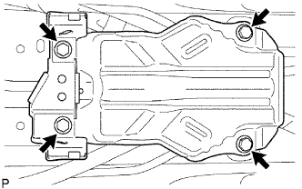 |
Install the No. 1 front floor side reinforcement with the 2 bolts.
Install the No. 1 console box mounting bracket with the 2 bolts.
| 6. INSTALL YAW RATE SENSOR (w/ VSC) |
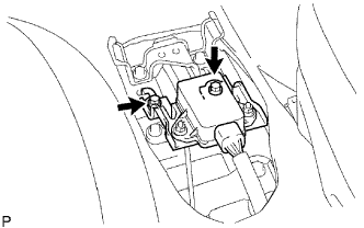 |
Install the sensor with the 2 bolts.
Connect the sensor connector.
| 7. INSTALL CENTER AIRBAG SENSOR ASSEMBLY |
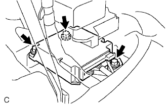 |
Install the airbag sensor with the 3 bolts.
Connect the airbag sensor connectors.
| 8. INSTALL FRONT FLOOR FOOTREST |
Attach the 2 clips to install the front floor footrest.
| 9. INSTALL FRONT SEAT ASSEMBLY LH/RH |
Install the front seat LH/RH (Click here).
| 10. INSTALL INSTRUMENT PANEL REINFORCEMENT ASSEMBLY |
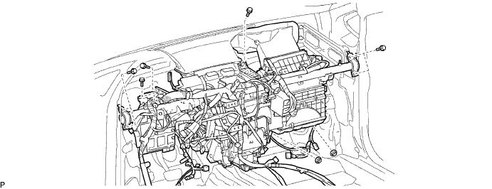
Install the instrument panel reinforcement with the 7 bolts.
Install the 2 nuts to the air conditioning unit and temporarily tighten them.
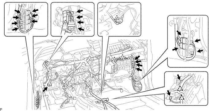
Connect each connector and install each clamp. Then connect the wire harness.
| 11. INSTALL NO. 1 INSTRUMENT PANEL BRACE SUB-ASSEMBLY |
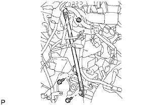 |
Install the instrument panel brace with the 2 bolts and nut.
Attach the clamp to connect the harness.
| 12. FULLY TIGHTEN AIR CONDITIONING UNIT |
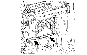 |
Fully tighten the air conditioning unit with the 2 nuts.
| 13. INSTALL STEERING COLUMN ASSEMBLY |
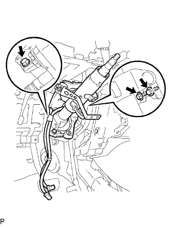 |
Install the steering column with the 3 bolts.
Connect the connectors and wire harness clamps to the steering column.
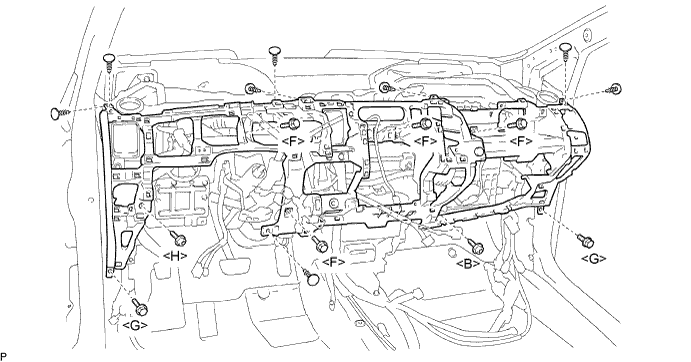
| 14. INSTALL LOWER INSTRUMENT PANEL SUB-ASSEMBLY |
Install the instrument panel.
Connect all the connectors and attach all the clamps.
Install the 2 screws.
Install the 6 bolts.
Install the 8 clips to the duct and lower instrument panel.
| 15. INSTALL SHIFT LEVER ASSEMBLY |
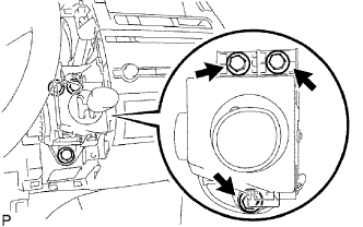 |
Connect the 2 connectors to the shift lever.
Install the shift lever with the 3 bolts.
| 16. INSTALL POWER STEERING ECU |
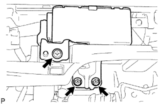 |
Install the ECU with the 3 screws.
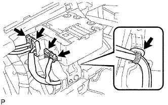 |
Connect the 4 ECU connectors.
Install the torque sensor wire harness clamp to the ECU.
| 17. INSTALL INSTRUMENT PANEL SUB-ASSEMBLY |
Install the instrument panel (Click here).
| 18. INSTALL COOLER REFRIGERANT LIQUID PIPE E (TO COOLER UNIT) |
Remove the attached vinyl tape from the pipe's disconnected part.
Sufficiently apply compressor oil (ND-OIL 11) to 2 new O-rings and the pipe's connecting part.
Install the O-rings to the pipe.
Insert the pipe joint into the cooler unit fitting hole securely.
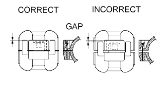 |
Using the piping clamp, connect the cooler unit refrigerant liquid pipe E.
| 19. INSTALL SUCTION HOSE SUB-ASSEMBLY |
| 20. INSPECT FOR REFRIGERANT LEAK |
After recharging the refrigerant gas, inspect for refrigerant leak gas using a halogen leak detector.
After recharging the refrigerant gas, prepare the vehicle for a refrigerant gas leakage check by making sure the following conditions are met.
The ignition switch is OFF.
The vehicle is in a place with good air ventilation and without any volatile gases, such as evaporated gasoline or exhaust gas. The detector is very sensitive to volatile gases. If volatile gases are unavoidable, the vehicle must be lifted up.
Some refrigerant remains in the refrigerant system.
The compressor is OFF and its pressure is approximately 392 to 588 kPa (4 to 6 kgf/cm2).
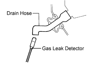 |
Bring the gas leak detector close to the drain hose with the detector's power off.
If a gas leak is not detected on the drain hose, remove the blower motor control from the cooling unit. Insert the gas leak detector sensor into the unit and perform the test.
Disconnect the pressure switch connector and wait for approximately 20 minutes. Bring the gas leak detector close to the pressure switch and perform the test.
| 21. POSITION SPIRAL CABLE SUB-ASSEMBLY |
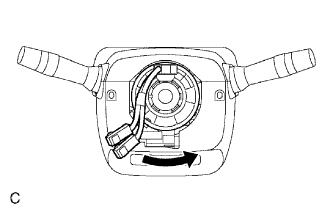 |
Slowly rotate the spiral cable counterclockwise by hand until it feels firm.
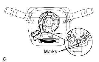 |
Rotate the spiral cable clockwise approximately 2.5 turns to align the marks.
| 22. INSTALL STEERING COLUMN COVER |
Engage the 4 claws to install the steering column upper cover and steering column lower cover.
| 23. INSTALL TILT LEVER BRACKET |
Install the tilt level bracket with the 2 screws.
| 24. INSTALL STEERING WHEEL ASSEMBLY |
Align the matchmarks on the steering wheel and steering main shaft.
Install the steering wheel with the set nut.
| 25. INSTALL STEERING PAD ASSEMBLY |
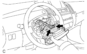 |
Support the steering pad with one hand as shown in the illustration.
Connect the 2 airbag connectors.
Connect the horn connector.
Install the steering pad after confirming that the circumference grooves of the screws are caught on the screw case.
Using a T30 "TORX" socket, install the 2 screws.
| 26. INSPECT STEERING PAD ASSEMBLY |
Check for cuts, cracks or discoloration on the steering pad outer surface and in the grooved portion.
Check that the horn sounds.
| 27. CONNECT CABLE TO NEGATIVE BATTERY TERMINAL |
| 28. INSTALL REAR NO. 3 FLOOR BOARD |
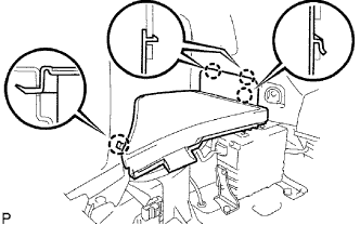 |
Install the floor board, and then attach the 4 claws.
| 29. INSTALL REAR DECK FLOOR BOX |
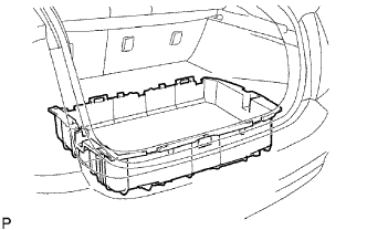 |
Install the rear deck floor box to the vehicle.
| 30. INSTALL REAR NO. 2 FLOOR BOARD |
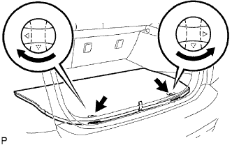 |
Install the floor board, and then lock the 2 cover knobs.
| 31. ADD ENGINE COOLANT |
| 32. CHARGE REFRIGERANT |
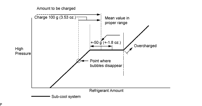
Perform vacuum purging using a vacuum pump.
Charge refrigerant HFC-134a (R134a).
| 33. INSPECT FOR ENGINE COOLANT LEAK |
| 34. WARM UP ENGINE |
| 35. INSPECT AND ADJUST PARKING BRAKE PEDAL TRAVEL |
Inspect and adjust the parking brake pedal travel (Click here).
| 36. CHECK SRS WARNING LIGHT |
Check the SRS warning light (Click here).
| 37. PERFORM CALIBRATION |
Perform calibration (Click here).