HYBRID / BATTERY CONTROL FRAME WIRE INSTALLATION
PROCEDURE

 82164
1.INSTALL FRAME WIRE
- CAUTION:
-
Wear insulated gloves.
- NOTICE:
-
Insulate the removed terminals with insulating tape.
Install a frame wire with the 4 new clamps as shown in the illustration.
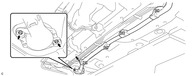
Insert the frame wire into the floor panel hole.
Install the 3 nuts as shown in the illustration.
- Torque:
- 8.4 N*m (85 kgf*cm, 74 in.*lbf)
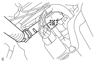
Connect the clamp as shown in the illustration.
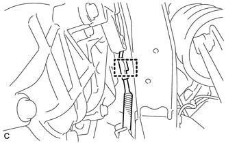
Connect the clamp as shown in the illustration.
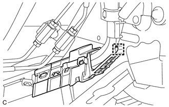
Connect the clamp as shown in the illustration.
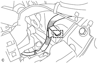
Connect the clamp as shown in the illustration.
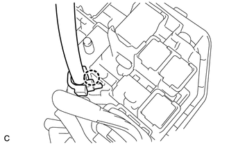
Connect the frame wire with the claw as shown in the illustration.
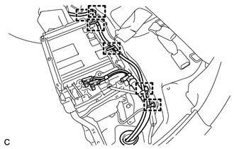
Connect the 6 clamps as shown in the illustration.
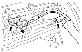
Connect the 2 connectors to the engine room junction block assembly as shown in the illustration.
- NOTICE:
- ·
Make sure that the ends of the frame wire are not crossed over each other.
·Be sure to connect the ends of the frame wire to the connect terminals.
| *1 | Shielded Wire Ground |
Connect the shielded wire ground as shown in the illustration.
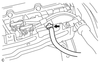
Connect the connector.
2.CONNECT CABLE TO POSITIVE AUXILIARY BATTERY TERMINAL
Connect the positive auxiliary battery terminal with the nut.
- Torque:
- 7.6 N*m (77 kgf*cm, 67 in.*lbf)
Install the terminal cover.
G92F1
3.INSTALL NO. 1 HYBRID BATTERY EXHAUST DUCT
G92N1A
4.INSTALL NO. 1 HYBRID VEHICLE BATTERY COVER PANEL LH
G9230
5.INSTALL BATTERY COOLING BLOWER ASSEMBLY
71033
6.INSTALL REAR SEAT CUSHION LEG SUB-ASSEMBLY
7.INSTALL REAR SEAT CUSHION ASSEMBLY
51201
8.INSTALL FRONT SUSPENSION CROSSMEMBER SUB-ASSEMBLY
G9110
9.INSTALL INVERTER BRACKET ASSEMBLY
G9200
10.INSTALL INVERTER WITH CONVERTER ASSEMBLY