1NZ-FXE ENGINE MECHANICAL ENGINE UNIT DISASSEMBLY
PROCEDURE

 19100P
1.REMOVE SPARK PLUG
12108
2.REMOVE OIL FILLER CAP SUB-ASSEMBLY
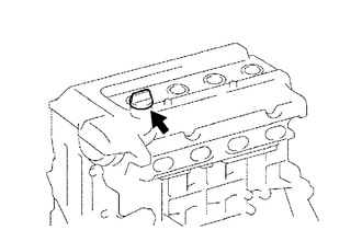
Remove the oil filler cap sub-assembly from the cylinder head cover.
12108A
3.REMOVE OIL FILLER CAP GASKET
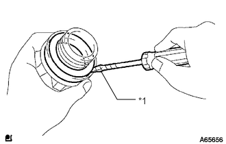
Using a screwdriver, remove the oil filler cap gasket from the oil filler cap.
| *1 | Protective Tape |
- HINT:
-
Wrap the screwdriver tip with protective tape before use.
11452
4.REMOVE ENGINE OIL LEVEL DIPSTICK GUIDE
11101E
5.REMOVE CAMSHAFT POSITION SENSOR
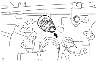
Remove the bolt and camshaft position sensor.
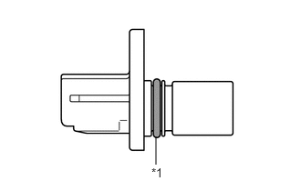
| *1 | O-ring |
Remove the O-ring from the camshaft position sensor.
- NOTICE:
- ·
Make sure to only remove the O-ring with bare hands.
·When removing the O-ring, be careful not to damage the O-ring groove of the camshaft position sensor.
·If the O-ring groove of the camshaft position sensor is damaged, replace the camshaft position sensor with a new one.
11101J
6.REMOVE CAMSHAFT TIMING OIL CONTROL VALVE ASSEMBLY
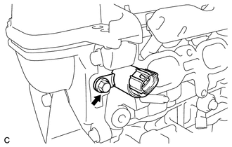
Remove the bolt and camshaft timing oil control valve assembly.
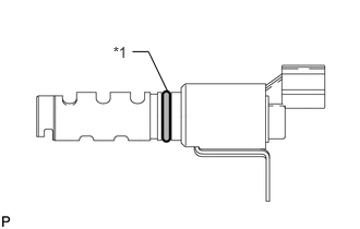
Remove the O-ring from the camshaft timing oil control valve assembly.
89615
7.REMOVE KNOCK CONTROL SENSOR
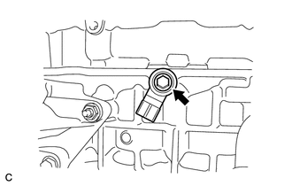
Remove the bolt and knock control sensor.
89422
8.REMOVE ENGINE COOLANT TEMPERATURE SENSOR
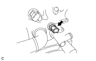
Using a 19 mm union nut wrench, remove the engine coolant temperature sensor and gasket.
83530
9.REMOVE ENGINE OIL PRESSURE SWITCH ASSEMBLY
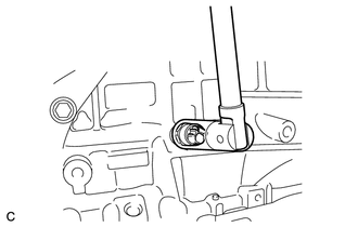
Using a 24 mm deep socket wrench, remove the engine oil pressure switch assembly.
15601
10.REMOVE OIL FILTER SUB-ASSEMBLY
15100Q
11.REMOVE CRANKSHAFT POSITION SENSOR
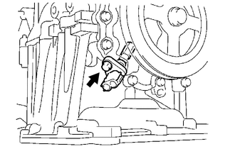
Remove the bolt and crankshaft position sensor.
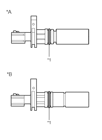
| *A | for Type A |
| *B | for Type B |
| *1 | O-ring |
Remove the O-ring from the crankshaft position sensor.
- NOTICE:
- ·
Make sure to only remove the O-ring with bare hands.
·When removing the O-ring, be careful not to damage the O-ring groove of the crankshaft position sensor.
·If the O-ring groove of the crankshaft position sensor is damaged, replace the crankshaft position sensor with a new one.
16031
12.REMOVE WATER INLET WITH THERMOSTAT SUB-ASSEMBLY
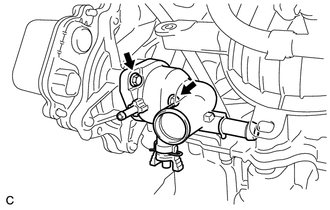
Remove the 2 bolts and water inlet with thermostat sub-assembly.
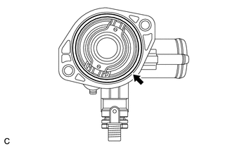
Remove the gasket from the water inlet with thermostat sub-assembly.
16100
13.REMOVE ENGINE WATER PUMP ASSEMBLY
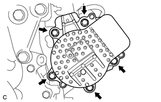
Remove the 5 bolts and engine water pump assembly.
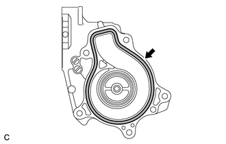
Remove the gasket from the engine water pump assembly.
16323
14.REMOVE WATER INLET HOUSING
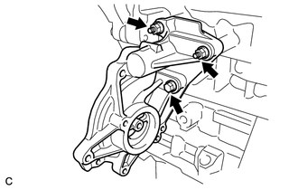
Remove the bolt, 2 nuts and water inlet housing.
Remove the gasket.
12315A
15.REMOVE ENGINE MOUNTING BRACKET RH
12204
16.REMOVE VENTILATION VALVE SUB-ASSEMBLY
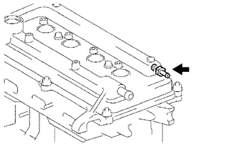
Using a 19 mm deep socket wrench, remove the ventilation valve sub-assembly from the cylinder head cover sub-assembly.
11201
17.REMOVE CYLINDER HEAD COVER SUB-ASSEMBLY
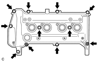
Remove the 9 bolts, 2 seal washers, 2 nuts and cylinder head cover sub-assembly.
Remove the gasket from the cylinder head cover sub-assembly.
13407
18.REMOVE CRANKSHAFT DAMPER SUB-ASSEMBLY
Set the No. 1 cylinder to TDC/compression.
Turn the crankshaft damper until its notch and timing mark "0" of the timing chain cover are aligned.
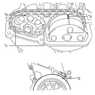
Check that the timing marks on both the camshaft timing sprocket and the camshaft timing gear are facing upward as shown in the illustration.
| *a | Timing Mark |
| *b | Timing Mark (Rectangle) |
| *c | Mark (Circle) |
| *d | Timing Notch |
- HINT:
- ·
There are 3 marks on the camshaft timing sprocket. Make sure that the timing mark (rectangle) is at the top.
·If not, turn the crankshaft 1 complete revolution (360°) and align the marks as above.
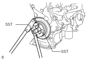
Using SST, hold the crankshaft damper sub-assembly in place and loosen the bolt.
- SST
- 09213-58012 (91111-50845)
09330-00021
- NOTICE:
-
When installing SST, be careful that the bolt which holds SST does not interfere with the chain cover.
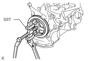
Using SST, remove the crankshaft damper sub-assembly and bolt.
- SST
- 09950-50013 (09951-05010, 09952-05010, 09953-05020, 09954-05021)
- HINT:
-
Apply a lubricant to the threads and end of SST.
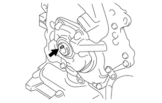
Remove the crankshaft straight pin.
15100
19.REMOVE TIMING CHAIN COVER
20.REMOVE SCREW PLUG
15100C
21.REMOVE OIL PUMP SEAL
13540
22.REMOVE NO. 1 CHAIN TENSIONER ASSEMBLY
13559
23.REMOVE CHAIN TENSIONER SLIPPER
13561
24.REMOVE NO. 1 CHAIN VIBRATION DAMPER
13506
25.REMOVE CHAIN SUB-ASSEMBLY
23814B
26.REMOVE FUEL DELIVERY PIPE
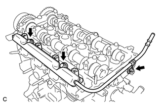
Remove the 3 bolts and fuel delivery pipe.
23891
27.REMOVE FUEL DELIVERY SPACER
23291
28.REMOVE INJECTOR VIBRATION INSULATOR
23250
29.REMOVE FUEL INJECTOR ASSEMBLY
13512
30.REMOVE NO. 2 CAMSHAFT
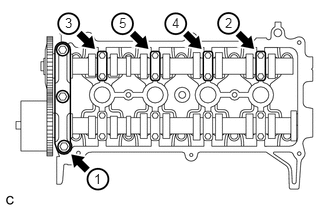
Using several steps, uniformly loosen and remove the 11 bolts in the sequence shown in the illustration. Then remove the No. 1 camshaft bearing cap and 4 No. 2 camshaft bearing caps.
- NOTICE:
-
Uniformly loosen the bolts while keeping the No. 2 camshaft level.
13523
31.REMOVE CAMSHAFT TIMING GEAR OR SPROCKET
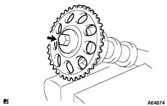
Clamp the No. 2 camshaft in a vise.
- NOTICE:
-
Be careful not to damage the No. 2 camshaft.
Remove the bolt and camshaft timing gear or sprocket.
13511
32.REMOVE CAMSHAFT
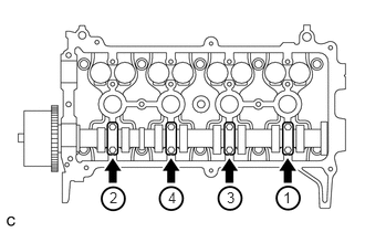
Using several steps, uniformly loosen and remove the 8 bolts in the sequence shown in the illustration. Then remove the 4 No. 2 camshaft bearing caps.
- NOTICE:
-
Uniformly loosen the bolts while keeping the camshaft level.
13050
33.INSPECT CAMSHAFT TIMING GEAR ASSEMBLY
13050
34.REMOVE CAMSHAFT TIMING GEAR ASSEMBLY
11101
35.REMOVE CYLINDER HEAD SUB-ASSEMBLY
11115
36.REMOVE CYLINDER HEAD GASKET
15600A
37.REMOVE OIL FILTER UNION
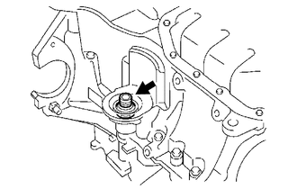
Using a 12 mm hexagon socket wrench, remove the oil filter union.
12102A
38.REMOVE NO. 2 OIL PAN SUB-ASSEMBLY
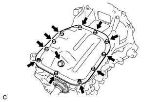
Remove the oil pan drain plug and gasket.
Remove the 9 bolts and 2 nuts.
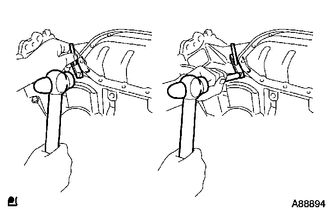
Insert the blade of an oil pan seal cutter between the oil pan and No. 2 oil pan sub-assembly, cut the sealer and remove the No. 2 oil pan sub-assembly.
- NOTICE:
-
Be careful not to damage the oil pan and No. 2 oil pan sub-assembly.
15104
39.REMOVE OIL STRAINER SUB-ASSEMBLY
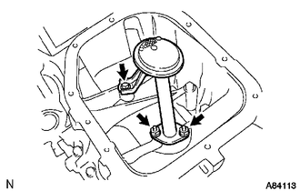
Remove the bolt, 2 nuts, oil strainer sub-assembly and gasket.
12101
40.REMOVE OIL PAN SUB-ASSEMBLY
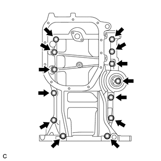
Loosen and remove the 13 bolts uniformly in several steps.
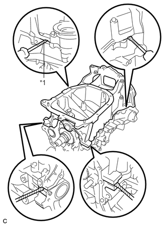
Using a screwdriver, remove the oil pan sub-assembly by prying between the cylinder block and oil pan sub-assembly.
| *1 | Protective Tape |
- NOTICE:
-
Be careful not to damage the contact surfaces of the oil pan sub-assembly and cylinder block.
- HINT:
-
Wrap the screwdriver tip with protective tape before use.
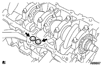
Remove the 2 O-rings from the cylinder block.
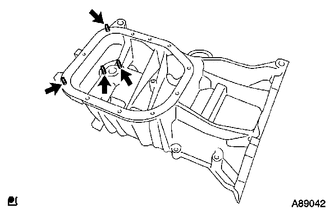
Using an E5 "TORX" socket wrench, remove the 4 stud bolts.
11401L
41.REMOVE REAR ENGINE OIL SEAL
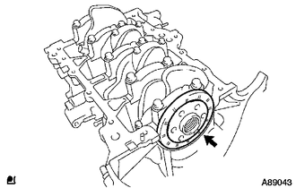
Remove the rear engine oil seal.