BRAKE SYSTEM (OTHER) BRAKE PEDAL(for RHD) INSTALLATION
PROCEDURE

 1.INSTALL BRAKE PEDAL SUPPORT ASSEMBLY
Install the brake pedal support assembly with the 4 nuts.
- Torque:
- 9.0 N*m (92 kgf*cm, 80 in.*lbf)
Engage the wire harness clamp to install it to the stud bolt of the brake booster with master cylinder assembly.
Install the bolt to secure the brake pedal support assembly to the instrument panel reinforcement assembly.
- Torque:
- 24 N*m (241 kgf*cm, 17 ft.*lbf)
Engage the clamp to the brake pedal support assembly.
47264A
2.INSTALL PUSH ROD PIN
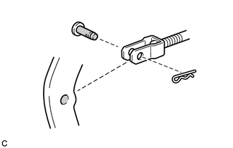
Apply lithium soap base glycol grease to the push rod pin and installation hole of the brake pedal sub-assembly.

|
Lithium Soap Base Glycol Grease |
Install the push rod pin and a new clip to connect the push rod clevis to the brake pedal support assembly.
- NOTICE:
-
Insert the push rod pin in the correct direction.
47101A
3.INSTALL BRAKE PEDAL RETURN SPRING
Install the brake pedal return spring to the brake pedal support assembly.
84345
4.INSTALL STOP LIGHT SWITCH MOUNTING ADJUSTER
84340
5.INSTALL STOP LIGHT SWITCH ASSEMBLY
89510D
6.INSTALL BRAKE PEDAL STROKE SENSOR ASSEMBLY
55404D
7.INSTALL INSTRUMENT CLUSTER FINISH PANEL SUB-ASSEMBLY
- HINT:
-
Use the same procedure for LHD and RHD (See page Vehicle Interior>METER / GAUGE / DISPLAY>COMBINATION METER>INSTALLATION).
8.CONNECT CABLE TO NEGATIVE AUXILIARY BATTERY TERMINAL
9.INSPECT AND ADJUST BRAKE PEDAL
10. PERFORM INITIALIZATION AND CALIBRATION OF LINEAR SOLENOID VALVE