BRAKE SYSTEM (OTHER) BRAKE BOOSTER PUMP(for RHD) REMOVAL
PROCEDURE

 1. PRECAUTION
- NOTICE:
-
After turning the power switch off, waiting time may be required before disconnecting the cable from the negative (-) auxiliary battery terminal. Therefore, make sure to read the disconnecting the cable from the negative (-) auxiliary battery terminal notices before proceeding with work (See page General>INTRODUCTION>REPAIR INSTRUCTION>PRECAUTION).
2. DISABLE BRAKE CONTROL
3.REMOVE WINDSHIELD WIPER MOTOR AND LINK ASSEMBLY
55722C
4.REMOVE INNER COWL TOP TO COWL BRACE
55735B
5.REMOVE FRONT AIR SHUTTER SEAL
55815E
6.REMOVE FRONT NO. 1 VENTILATOR SEAL
55701J
7.REMOVE OUTER COWL TOP PANEL SUB-ASSEMBLY
8.DRAIN BRAKE FLUID
- NOTICE:
-
If brake fluid leaks onto any painted surface, immediately clean it off.
44571
9.DISCONNECT BRAKE ACTUATOR HOSE
Disconnect the 2 connectors from the ECM (See page Engine / Hybrid System>1NZ-FXE (ENGINE CONTROL)>ECM>REMOVAL).
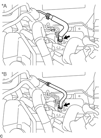
Move the clip and disconnect the brake actuator hose from the brake booster pump assembly.
| *A | for Type A |
| *B | for Type B |
47311
10.DISCONNECT FRONT NO. 1 BRAKE TUBE
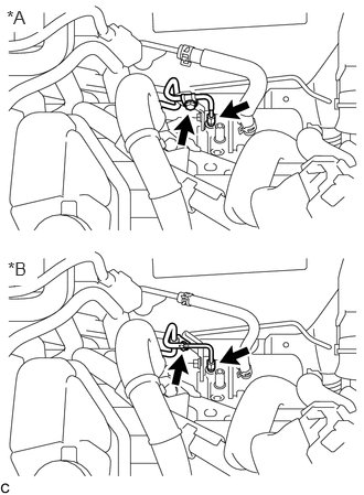
Using a union nut wrench, disconnect the front No. 1 brake tube from the brake booster pump assembly.
| *A | for Type A |
| *B | for Type B |
Remove the bolt to separate the front No. 1 brake tube from the No. 1 brake tube clamp bracket.
47381
11.REMOVE NO. 1 BRAKE TUBE CLAMP BRACKET
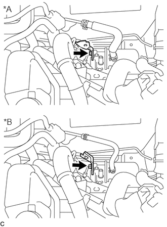
Remove the bolt and No. 1 brake tube clamp bracket.
| *A | for Type A |
| *B | for Type B |
47070
12.REMOVE BRAKE BOOSTER PUMP ASSEMBLY
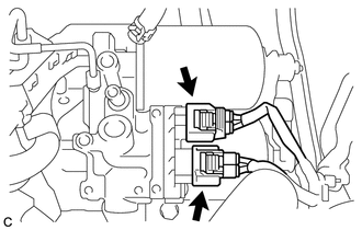
Disconnect the 2 connectors from the brake booster pump assembly.
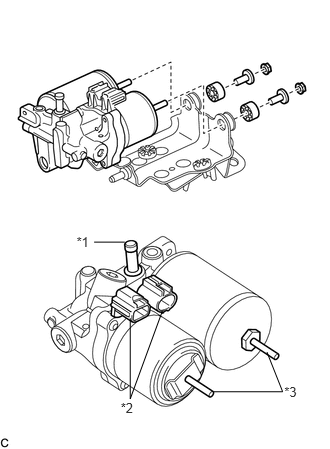
Remove the 2 nuts, brake booster pump assembly, 2 brake actuator case collars and 2 brake booster pump bushings from the brake actuator bracket assembly.
| *1 | Union |
| *2 | Connector |
| *3 | Stud |
- NOTICE:
- ·
Do not carry the brake booster pump assembly by the parts shown in bold (*1, *2 and *3) in the illustration.
·Do not drop the brake booster pump assembly when carrying it. If the brake booster pump assembly has been dropped, replace it with a new one.
·Do not kink or damage the brake lines. If they are damaged, replace them with new ones.
·Be careful not to allow any brake fluid to enter the connector.
13.REMOVE FRONT WHEEL LH
51442C
14.REMOVE ENGINE UNDER COVER LH
44590
15.REMOVE BRAKE ACTUATOR BRACKET ASSEMBLY
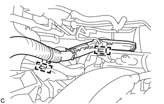
Disengage the 2 clamps to separate the frame wire from the brake actuator bracket assembly.
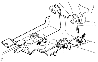
Remove the 3 bolts and brake actuator bracket assembly.
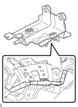
Disengage the clamp to separate the frame wire from the brake actuator bracket assembly.
- NOTICE:
-
Do not kink or damage the brake lines.