HEATING / AIR CONDITIONING AIR CONDITIONING UNIT INSTALLATION
PROCEDURE

 87201B
1.INSTALL NO. 2 AIR DUCT SUB-ASSEMBLY
Engage the 3 claws to install the No. 2 air duct sub-assembly.
- NOTICE:
-
If any of the claws of the No. 2 air duct subassembly are cracked or deformed, make sure to replace the air duct with a new one. Failure to do so may cause the No. 2 air duct subassembly to fall off or noise to occur.
87201F
2.INSTALL NO. 3 AIR DUCT SUB-ASSEMBLY
Engage the 3 claws to install the No. 3 air duct sub-assembly.
- NOTICE:
-
If any of the claws of the No. 3 air duct subassembly are cracked or deformed, make sure to replace the air duct with a new one. Failure to do so may cause the No. 2 air duct subassembly to fall off or noise to occur.
82210K
3.INSTALL AIR CONDITIONING HARNESS ASSEMBLY
Connect each connector.
Engage each clamp to install the air conditioning harness assembly.
88650N
4.INSTALL AIR CONDITIONING AMPLIFIER ASSEMBLY
Temporarily install the air conditioning amplifier assembly as shown in the illustration.
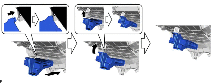
Install the air conditioning amplifier assembly with the screw.
Connect the connector.
88897P
5.INSTALL ASPIRATOR
Engage the 2 claws and install the aspirator.
87050
6.INSTALL AIR CONDITIONING RADIATOR ASSEMBLY
Install the air conditioning radiator assembly with the 3 screws.
Connect the connector.
7.TEMPORARILY TIGHTEN AIR CONDITIONER UNIT ASSEMBLY
Temporarily tighten the air conditioning unit with the 3 bolts and nut.
- NOTICE:
-
To prevent damage to the installation bracket for the air conditioning unit, be sure to support the air conditioning unit in place.
88539J
8.CONNECT DRAIN COOLER HOSE
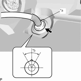
Install the drain cooler hose as shown in the illustration.
| *a | UP Mark |
| *b | 60° |
- NOTICE:
- ·
Install the drain hose with its UP mark facing upward, within the 60 degree range shown in the illustration.
·Install the drain hose without twisting it.
55950G
9.INSTALL DEFROSTER NOZZLE ASSEMBLY
Engage the 2 claws and 3 guides to install the defroster nozzle assembly.
55330B
10.INSTALL INSTRUMENT PANEL REINFORCEMENT ASSEMBLY
Install the instrument panel reinforcement with the 8 bolts.
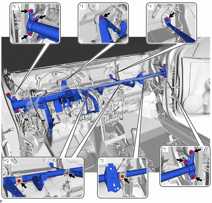
| *1 | Bolt | *2 | Screw |
- Torque:
- for Type A : 19 N*m (194 kgf*cm, 14 ft.*lbf)
- for Type B : 29 N*m (296 kgf*cm, 21 ft.*lbf)
- NOTICE:
-
 0.406,1.167 0.625,1.594 0.219,0.427 10 false a 2.021,1.219 2.24,1.646 0.219,0.427 10 false b 1.052,0.354 1.406,0.813 0.354,0.458 12 false *A 2.677,0.365 3.031,0.823 0.354,0.458 12 false *B
-
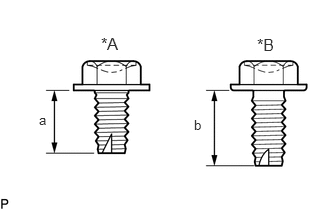
There are three types of bolts and the tightening torque depends on the type of bolt used as shown in the illustration. Therefore, confirm the tightening torque before installing the bolt.
Text in Illustration *A for Type A *B for Type B
Area Measurement a 14.5 to 15.5 mm (0.571 to 0.610 in.) b 17.5 to 18.5 mm (0.689 to 0.728 in.)
Temporarily tighten the 3 screws.
82141
11.CONNECT INSTRUMENT PANEL WIRE (for LHD)
Engage each clamp.
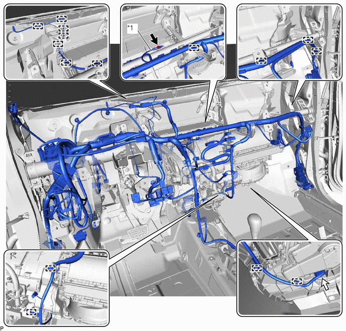
| *1 | Earth Wire | - | - |
Connect the connector.
Install the earth wire with the bolt.
- Torque:
- 8.4 N*m (86 kgf*cm, 74 in.*lbf)
Engage each clamp.
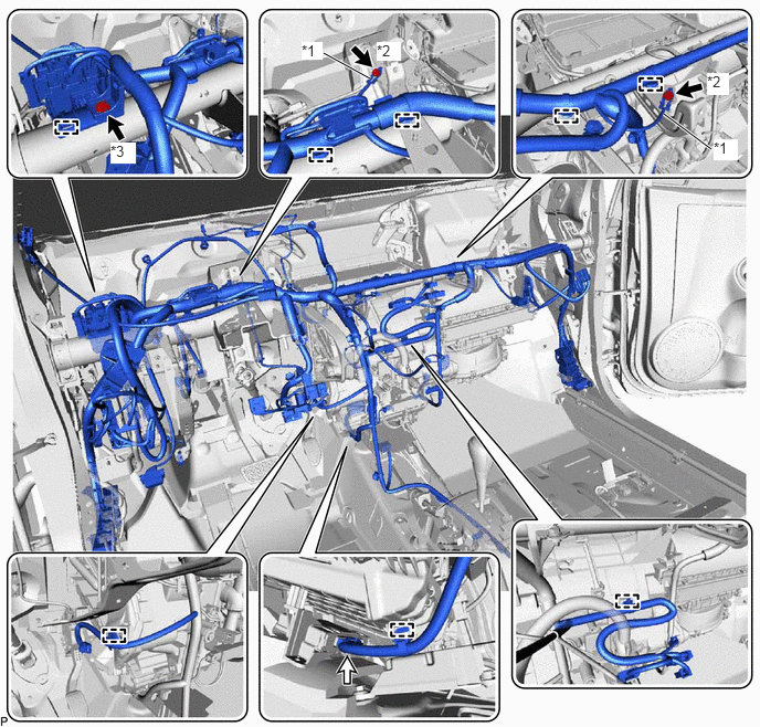
| *1 | Earth Wire | *2 | Bolt <A> |
| *2 | Bolt <B> | - | - |
Connect the connector.
Install the bolt <B>.
- Torque:
- 5.5 N*m (56 kgf*cm, 49 in.*lbf)
Install the 2 earth wires with the 2 bolts <A>.
- Torque:
- 8.4 N*m (86 kgf*cm, 74 in.*lbf)
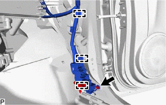
for RH Side:
Engage each clamp and connect the connector holder.
Install the bolt.
- Torque:
- 8.4 N*m (86 kgf*cm, 74 in.*lbf)
Connect each connector.
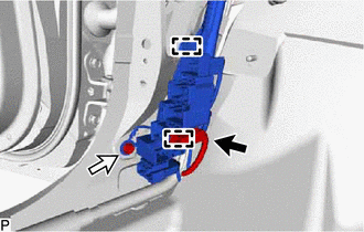
for LH Side:
Engage each clamp and connect the connector holder.
Connect the connector to the connector holder.
Install the bolt.
- Torque:
- 8.4 N*m (86 kgf*cm, 74 in.*lbf)
Connect each connector.
82141
12.CONNECT INSTRUMENT PANEL WIRE (for RHD)
Engage each clamp.
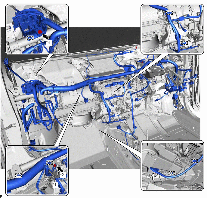
| *1 | Earth Wire | *2 | Bolt <A> |
| *3 | Bolt <B> | - | - |
Connect the connector.
Install the bolt <B>.
- Torque:
- 5.5 N*m (56 kgf*cm, 49 in.*lbf)
Install the earth wire with the bolt <A>.
- Torque:
- 8.4 N*m (86 kgf*cm, 74 in.*lbf)
Engage each clamp.
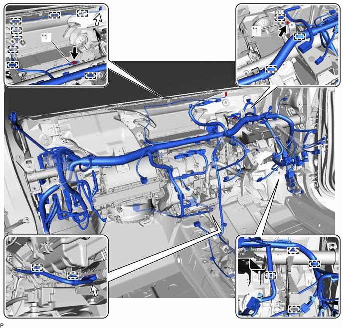
| *1 | Earth Wire | - | - |
Connect each connector.
Install the 2 earth wires with the 2 bolts.
- Torque:
- 8.4 N*m (86 kgf*cm, 74 in.*lbf)
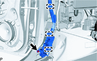
for LH Side:
Engage each clamp and connect the connector holder.
Install the bolt.
- Torque:
- 8.4 N*m (86 kgf*cm, 74 in.*lbf)
Connect each connector.
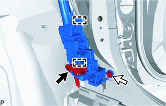
for RH Side:
Engage each clamp and connect the connector holder.
Connect the connector to the connector holder.
Install the bolt.
- Torque:
- 8.4 N*m (86 kgf*cm, 74 in.*lbf)
Connect each connector.
55306A
13.INSTALL NO. 1 INSTRUMENT PANEL BRACE SUB-ASSEMBLY (for LHD)
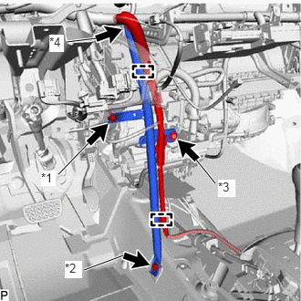
Install the No. 1 instrument panel brace sub-assembly with the bolt <A>, <B>, screw and nut.
| *1 | Bolt <A> |
| *2 | Bolt <B> |
| *3 | Screw |
| *4 | Nut |
- Torque:
- Bolt <B> : 19 N*m (194 kgf*cm, 14 ft.*lbf)
- Nut : 13 N*m (133 kgf*cm, 10 ft.*lbf)
- HINT:
-
Do not fully tighten the screw.
Engage each clamp.
55306A
14.INSTALL NO. 1 INSTRUMENT PANEL BRACE SUB-ASSEMBLY (for RHD)
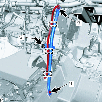
Install the No. 1 instrument panel brace sub-assembly with the bolt, screw and nut.
| *1 | Bolt |
| *2 | Screw |
| *3 | Nut |
- Torque:
- Bolt : 19 N*m (194 kgf*cm, 14 ft.*lbf)
- Nut : 13 N*m (133 kgf*cm, 10 ft.*lbf)
- HINT:
-
Do not fully tighten the screw.
Engage each clamp.
15.INSTALL AIR CONDITIONER UNIT ASSEMBLY
Tighten install the 2 No. 1 air duct bolts.
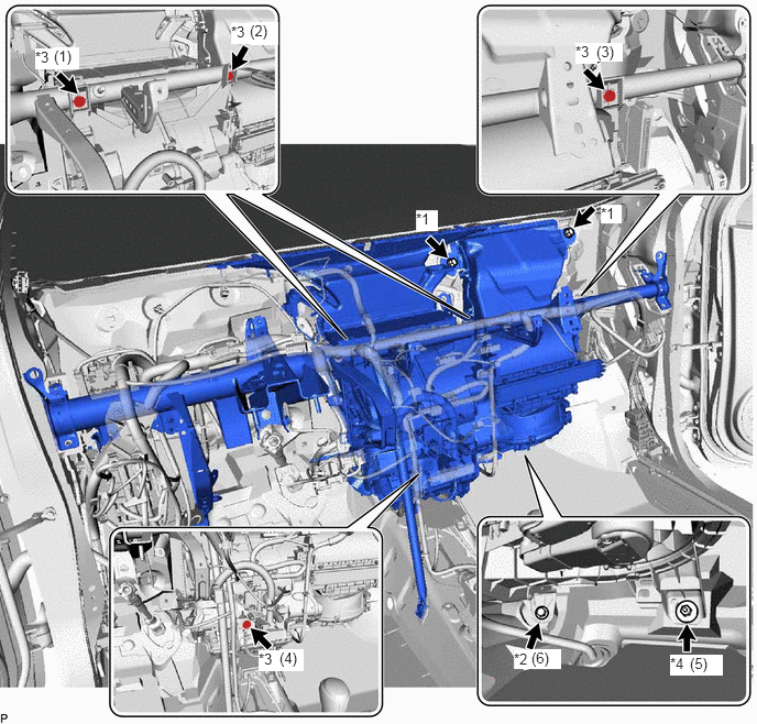
| *1 | No. 1 air duct bolt | *2 | Bolt |
| *3 | Screw | *4 | Nut |
- Torque:
- 9.8 N*m (100 kgf*cm, 87 in.*lbf)
Install the bolt, nut and 4 screws in the order shown in the illustration.
- Torque:
- Bolt : 9.8 N*m (100 kgf*cm, 87 in.*lbf)
- Screw (1), (2), (3) : 4.0 N*m (41 kgf*cm, 35 in.*lbf)
58510D
16.INSTALL FRONT FLOOR CARPET ASSEMBLY
Install the front floor carpet assembly.
899A0A
17.INSTALL NO. 2 INDOOR ELECTRICAL KEY ANTENNA ASSEMBLY
899A0
18.INSTALL NO. 1 INDOOR ELECTRICAL KEY ANTENNA ASSEMBLY
89650
19.INSTALL POWER STEERING ECU ASSEMBLY (for LHD)
89650
20.INSTALL POWER STEERING ECU ASSEMBLY (for RHD)
82730
21.INSTALL INSTRUMENT PANEL JUNCTION BLOCK ASSEMBLY (for LHD)
82730
22.INSTALL INSTRUMENT PANEL JUNCTION BLOCK ASSEMBLY (for RHD)
82141
23.CONNECT INSTRUMENT PANEL WIRE
89681A
24.INSTALL POWER MANAGEMENT CONTROL ECU
25.INSTALL STEERING COLUMN ASSEMBLY
55303B
26.INSTALL LOWER INSTRUMENT PANEL SUB-ASSEMBLY
87209
27.CONNECT WATER HOSE SUB-ASSEMBLY
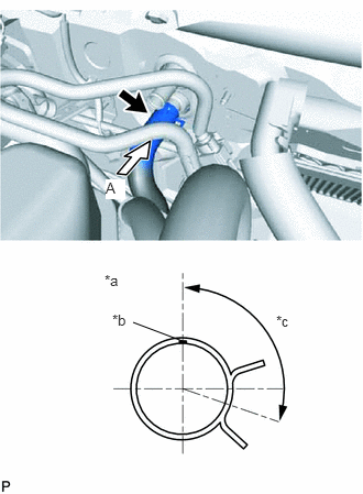
Connect the water hose with the marking (white) facing up and engage the clip within the area shown in the illustration.
| *a | View A |
| *b | Water Hose Sub-assembly Marking (White) |
| *c | Clip installation angle (60° to 150°) |
- NOTICE:
-
Do not apply excessive force to the water hose sub-assembly.
87246A
28.CONNECT HEATER WATER OUTLET HOSE A
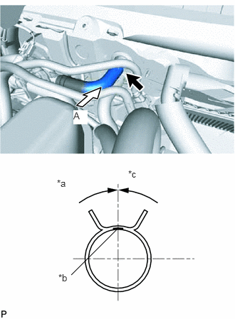
Connect heater water outlet hose A with the marking (purple) facing up and engage the clip within the area shown in the illustration.
| *a | View A |
| *b | Heater Water Outlet Hose A Marking (Purple) |
| *c | Clip installation angle (-45° to 45°) |
- NOTICE:
-
Do not apply excessive force to heater water outlet hose A.
88706
29.CONNECT LIQUID PIPE SUB-ASSEMBLY
Remove the vinyl tape from the liquid pipe sub-assembly.
Sufficiently apply compressor oil to a new O-ring and fitting surface of the liquid pipe sub-assembly.
- Compressor oil:
ND-OIL 11 or equivalent
Install the O-ring to the liquid pipe sub-assembly.
Install the liquid pipe sub-assembly.
88707
30.CONNECT SUCTION PIPE SUB-ASSEMBLY
Remove the vinyl tape from the suction pipe sub-assembly.
Sufficiently apply compressor oil to a new O-ring and fitting surface of the suction pipe sub-assembly.
- Compressor oil:
ND-OIL 11 or equivalent
Install the O-ring to the suction pipe sub-assembly.
Connect the suction pipe sub-assembly.
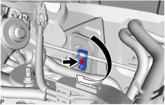
Rotate the hook connector in the direction indicated by the arrow in the illustration.
Insert the pipe joint into the fitting hole securely and tighten the bolt.
- Torque:
- 9.8 N*m (100 kgf*cm, 87 in.*lbf)
55701J
31.INSTALL OUTER COWL TOP PANEL SUB-ASSEMBLY (for LHD)
55701J
32.INSTALL OUTER COWL TOP PANEL SUB-ASSEMBLY (for RHD)
55815E
33.INSTALL FRONT NO. 1 VENTILATOR SEAL (for LHD)
55815E
34.INSTALL FRONT NO. 1 VENTILATOR SEAL (for RHD)
55735B
35.INSTALL FRONT AIR SHUTTER SEAL (for LHD)
55735B
36.INSTALL FRONT AIR SHUTTER SEAL (for RHD)
55722C
37.INSTALL INNER COWL TOP TO COWL BRACE (for LHD)
55722C
38.INSTALL INNER COWL TOP TO COWL BRACE (for RHD)
39.INSTALL WINDSHIELD WIPER MOTOR AND LINK
40.INSPECT FOR COOLANT LEAK (for Engine)
41.INSPECT ENGINE COOLANT LEVEL IN RESERVOIR (for Engine)
42.CHARGE AIR CONDITIONING SYSTEM WITH REFRIGERANT
43.WARM UP COMPRESSOR
44.INSPECT FOR REFRIGERANT LEAK