METER / GAUGE / DISPLAY METER / GAUGE SYSTEM Steering Pad Switch Circuit
DESCRIPTION
The combination meter assembly and steering pad switch RH are connected via direct line. The multi-information display and illumination level in the combination meter assembly are operated using the switches of the steering pad switch RH.
WIRING DIAGRAM
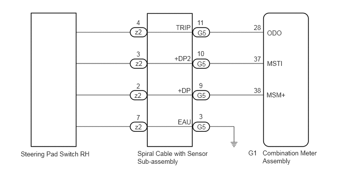
PROCEDURE
Remove the steering pad switch RH.
Click hereSteering>STEERING COLUMN>STEERING PAD SWITCH>REMOVAL
Inspect the steering pad switch RH.
Click hereSteering>STEERING COLUMN>STEERING PAD SWITCH>INSPECTION
- Result:
Proceed to OK NG
OK
NG
Remove the spiral cable with sensor sub-assembly.
Click hereVehicle Interior>SUPPLEMENTAL RESTRAINT SYSTEMS>SPIRAL CABLE>REMOVAL
Inspect the spiral cable with sensor sub-assembly.
Click hereVehicle Interior>SUPPLEMENTAL RESTRAINT SYSTEMS>SPIRAL CABLE>INSPECTION
- Result:
Proceed to OK NG
OK
NG
Disconnect the G1 combination meter assembly connector.
Measure the resistance according to the value(s) in the table below.
- Standard Resistance:
Tester Connection Condition Specified Condition G5-11 (TRIP) - G1-28 (ODO) Always Below 1 Ω G5-10 (+DP2) - G1-37 (MSTI) Always Below 1 Ω G5-9 (+DP) - G1-38 (MSM+) Always Below 1 Ω G5-11 (TRIP) or G1-28 (ODO) - Body ground Always 10 kΩ or higher G5-10 (+DP2) or G1-37 (MSTI) - Body ground Always 10 kΩ or higher G5-9 (+DP) or G1-38 (MSM+) - Body ground Always 10 kΩ or higher G5-3 (EAU) - Body ground Always Below 1 Ω
- Result:
Proceed to OK NG
OK
NG