HYBRID / BATTERY CONTROL HV BATTERY REMOVAL
PROCEDURE

 1. PRECAUTION
2. READ VALUE USING GTS
Connect the GTS to the DLC3.
Turn the power switch on (IG).
Enter the following menus: Powertrain / Hybrid Control / Data List / Temp of Batt TB 0 to 5.
Read the Data List.
- NOTICE:
-
If any of the temperatures listed in "Temp of Batt TB 0 to 5" are 50°C or more, leave the vehicle until the temperature drops to less than 50°C.
3. READ OUTPUT DTC
Check for DTCs (See page Engine / Hybrid System>HYBRID / BATTERY CONTROL>HYBRID BATTERY SYSTEM>DTC CHECK / CLEAR).
- NOTICE:
-
Check for DTCs and confirm that P0AA6 (Hybrid Battery Voltage System Isolation Fault) is not output before removing or installing internal battery components. If this DTC is output, perform troubleshooting for this DTC first.
G3834
4.REMOVE SERVICE PLUG GRIP
G9221
5.REMOVE INVERTER COVER
6.CHECK TERMINAL VOLTAGE
G9221
7.INSTALL INVERTER COVER
8.REMOVE FRONT SEAT ASSEMBLY RH
for Manual Seat:
(See page Vehicle Interior>SEAT>FRONT SEAT ASSEMBLY (for Manual Seat)>REMOVAL)
for Power Seat:
(See page Vehicle Interior>SEAT>FRONT SEAT ASSEMBLY (for Power Seat)>REMOVAL)
58534H
9.REMOVE CENTER FLOOR CARPET COVER LH
58533F
10.REMOVE CENTER FLOOR CARPET COVER RH
58804A
11.REMOVE UPPER CONSOLE PANEL SUB-ASSEMBLY
58817A
12.REMOVE FRONT NO. 2 CONSOLE BOX INSERT
58810J
13.REMOVE CONSOLE BOX ASSEMBLY
G920Q
14.REMOVE NO. 1 HYBRID BATTERY SHIELD SUB-ASSEMBLY
- CAUTION:
-
Wear insulated gloves.
- NOTICE:
- ·
When handling the HV battery, disconnect the high voltage connector of the battery smart unit to prevent the hybrid battery cell voltage from dropping.
·Insulate the removed connectors with insulating tape.
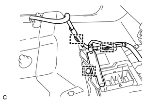
Disconnect the 3 clamps.
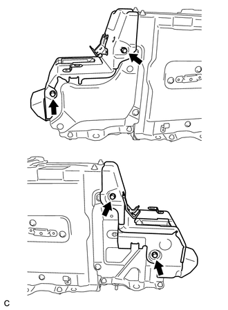
Remove the 4 bolts and No. 1 hybrid battery shield sub-assembly.
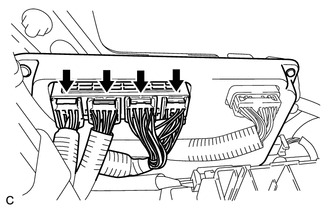
Disconnect the 4 connectors from the battery smart unit.
- NOTICE:
-
Insulate the removed connectors with insulating tape.
82164
15.DISCONNECT FRAME WIRE
- CAUTION:
-
Wear insulated gloves.
- NOTICE:
-
Insulate the removed terminals with insulating tape.
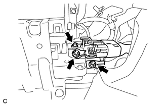
Using an insulated tool, remove the 3 nuts and disconnect the frame wire from the hybrid battery junction block assembly.
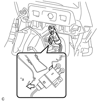
Install the frame wire as shown in the illustration.
| *a | Front of Vehicle |
G92F1
16.REMOVE NO. 1 HYBRID BATTERY EXHAUST DUCT
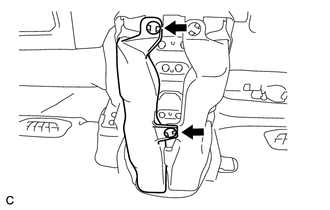
Remove the 2 clips and No. 1 hybrid battery exhaust duct.
G92D4
17.REMOVE NO. 4 HYBRID BATTERY INTAKE DUCT
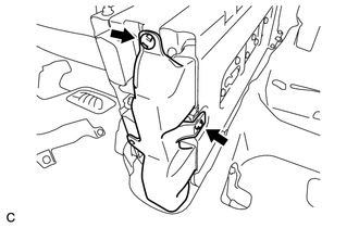
Remove the 2 clips and No. 4 hybrid battery intake duct.
G9510
18.REMOVE HV BATTERY
- CAUTION:
-
Wear insulated gloves.
- NOTICE:
- ·
Insulate the removed connectors and terminals with insulating tape.
·Since the HV battery is very heavy, 2 people are needed to remove the HV battery.
·Use cardboard or other similar material to protect the HV battery and vehicle body from damage.
·When moving the hybrid battery, make sure to use an engine lifter.
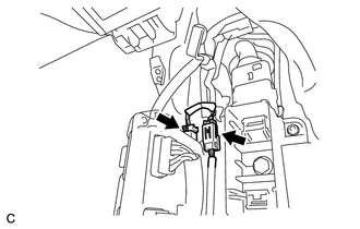
Disconnect the 2 connectors.
Disconnect the floor carpet from the HV battery.
Remove the 6 bolts.
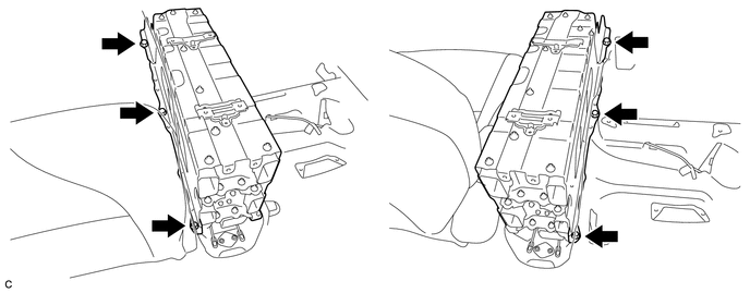
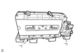
Remove the HV battery.
- HINT:
-
Be sure to place the HV battery on the attachment to prevent the guide pins from being damaged.
| *1 | Guide Pin |
G92N2
19.REMOVE NO. 2 HYBRID VEHICLE BATTERY COVER PANEL LH
- CAUTION:
-
Wear insulated gloves.
- NOTICE:
-
Insulate the removed connectors with insulating tape.
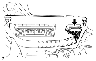
Disconnect the connector.
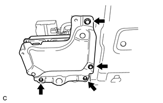
Remove the 4 bolts and No. 2 hybrid vehicle battery LH cover panel.
89892A
20.REMOVE BATTERY SMART UNIT
G920R
21.REMOVE NO. 2 HYBRID BATTERY SHIELD SUB-ASSEMBLY
- CAUTION:
-
Wear insulated gloves.
- NOTICE:
-
Insulate the removed connectors with insulating tape.
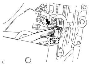
Disconnect the connector and clamp.
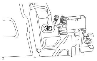
Disconnect the clamp.
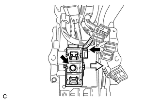
Disconnect the connector.
Remove the bolt and electric vehicle battery plug assembly as shown in the illustration.
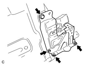
Remove the 4 bolts and No. 2 hybrid battery shield sub-assembly.
G92Z0
22.REMOVE HYBRID BATTERY JUNCTION BLOCK ASSEMBLY
G92X2
23.REMOVE NO. 2 HYBRID BATTERY PACK WIRE
- CAUTION:
-
Wear insulated gloves.
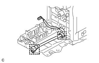
Disconnect the 2 clamps and remove the No. 2 hybrid battery pack wire.
24.PERFORM HV BATTERY RECOVERY INSPECTION
Before returning the HV battery, make sure to perform a recovery inspection (See page Engine / Hybrid System>HYBRID / BATTERY CONTROL>HV BATTERY>RECOVERY INSPECTION)